. A complete Parts List is available at www.MillerWelds.com
OM-272989 Page 24
5-9. Process/Polarity Table
Process Polarity
Cable Connections
Wire Drive Assembly Cable Work Cable
GMAW − Solid wire with shielding gas DCEP − Reverse polarity Connect to positive (+)
output receptacle
Connect to negative (−)
output receptacle
FCAW − Self-shielding wire − no
shielding gas
DCEN − Straight Polarity Connect to negative (−)
output receptacle
Connect to positive (+)
output receptacle
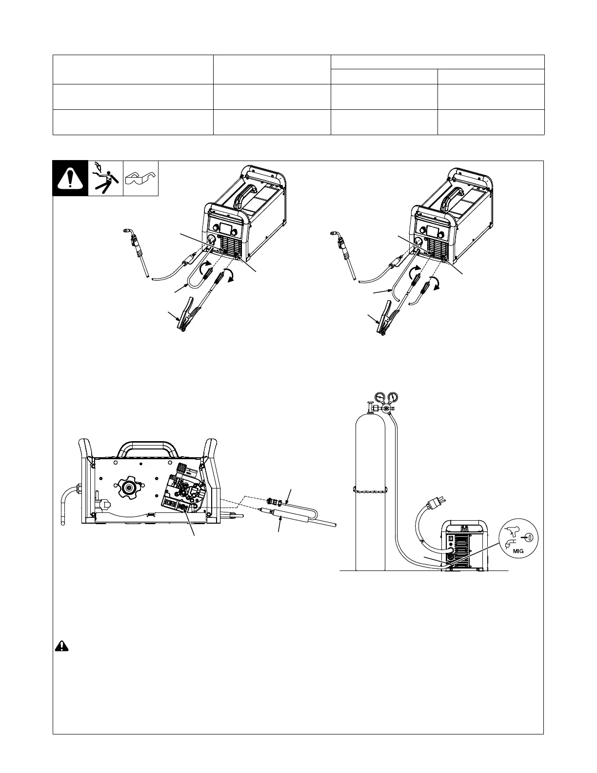
5-10. MIG Welding Connections
Ref. 275172A / Ref. 275167A / Ref. 275168A
! Turn off unit and disconnect input
power before making connections.
1 Positive Weld Output Receptacle
2 Negative Weld Output Receptacle
3 Wire Drive Assembly Cable
4 Work Clamp And Cable
Ensure all connections are tight.
5 Gun End
Connect gun end to drive assembly (see
Section 5-11).
6 Trigger Control Cable
7 Four Pin Trigger Control Cable
Receptacle
Route trigger control cable through MIG
gun hole.
Connect plug on end of cable to four pin
receptacle inside unit.
8 MIG Shielding Gas Connection
Use 75/25 mix or CO
2
shielding gas for
solid wire. Use Argon shielding gas for
aluminum wire with spool gun (see Section
5-12).
MIG − DCEP
(Direct Current Electrode Positive)
Flux-Cored − DCEN
(Direct Current Electrode Negative)
1
4
3
2
1
4
3
2
8
6
75