. A complete Parts List is available at www.MillerWelds.com
OM-272989 Page 35
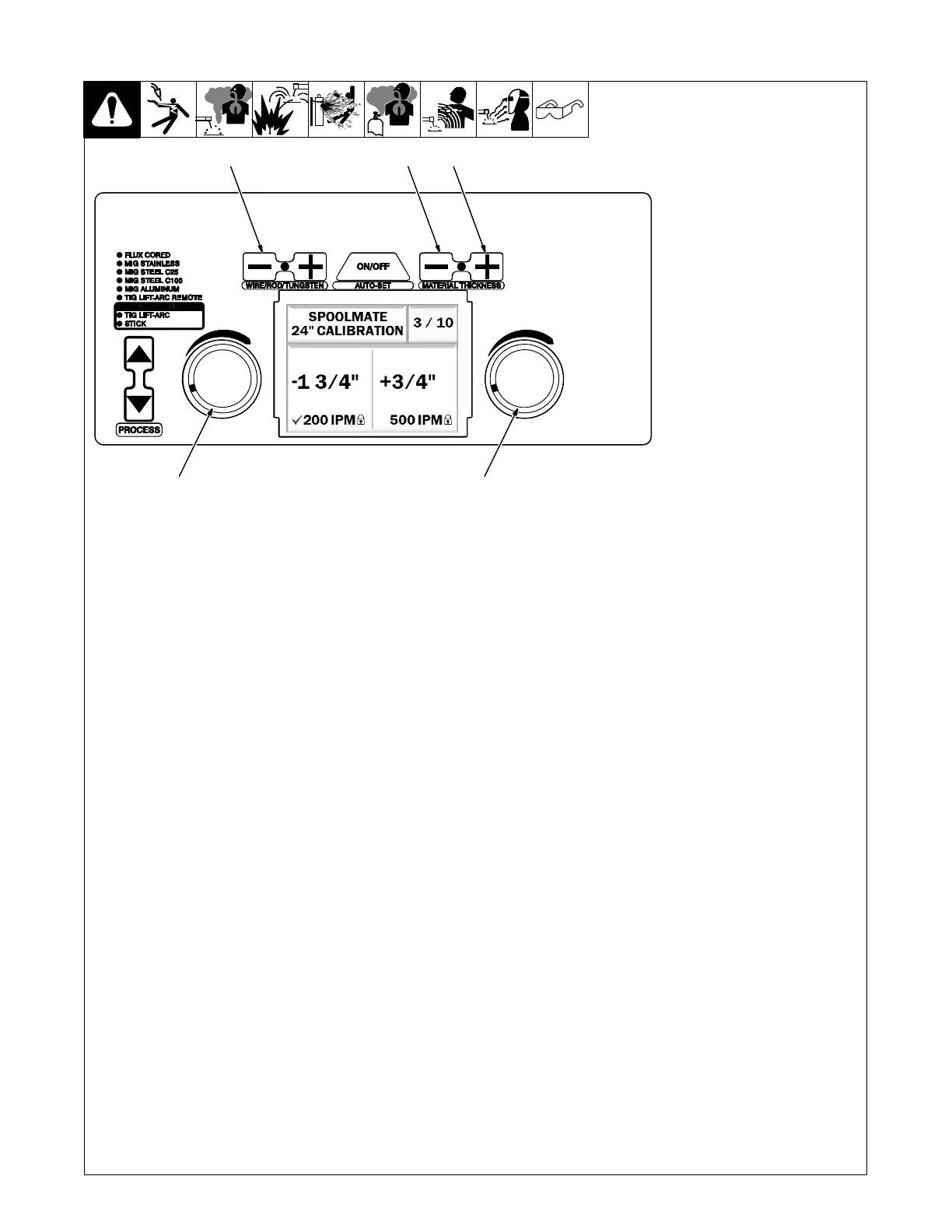
6-7. Spoolmatet 24 Inch Calibration (Menu 3 Of 10)
1 Wire/Rod/Tungsten Minus (−)
Button
2 Material Thickness Plus (+)
Button
3 Material Thickness Minus (−)
Button
4 Left Adjustment Knob
5 Right Adjustment Knob
. Spoolmate 100 and 150 drive
motors are unique to this weld-
ing power source. Motor cali-
bration is necessary any time a
different Spoolmate 100 or 150
is connected to the Multimatic
215.
Connect Spoolmate to unit.
Cut wire flush at nozzle.
Follow instructions in Section 6-4 to
enter the setup menu.
To perform a Spoolmate calibration
24 in. run-out test at 200 IPM, turn
left Adjustment knob, and verify that
a check mark appears next to 200
IPM.
Wait for the lock symbol to change
from unlocked to locked.
Cut wire flush at nozzle and then
trigger the Spoolmate.
Spoolmate will feed approximately
24 in. of wire through gun.
Cut wire flush at nozzle and mea-
sure run−out.
If wire length is not 24 in., use left
Adjustment knob to increase/de-
crease length of the run-out.
Wait for the lock symbol to change
from unlocked to locked, and repeat
the test.
To perform a Spoolmate calibration
24 in. run-out test at 500 IPM, turn
right Adjustment knob and verify
that a check mark appears next to
500 IPM.
Wait for the lock symbol to change
from unlocked to locked.
Cut wire flush at nozzle and then
trigger the Spoolmate.
Spoolmate will feed approximately
24 in. of wire through gun.
Cut wire flush at nozzle and mea-
sure run−out.
If wire length is not 24 in., use right
Adjustment knob to increase/de-
crease length of the run−out.
Wait for the lock symbol to change
from unlocked to locked, and repeat
the test.
To exit menu, simultaneously press
and release the Wire/Rod/Tung-
sten Minus (−) button and Material
Thickness Plus (+) button, or turn
unit off and on.
Ref. 271491A
1 23
4
5