Disassembly of DP-9900Plus/DP-9900
3-17
M4×8 screws and take out the whole cabinet.
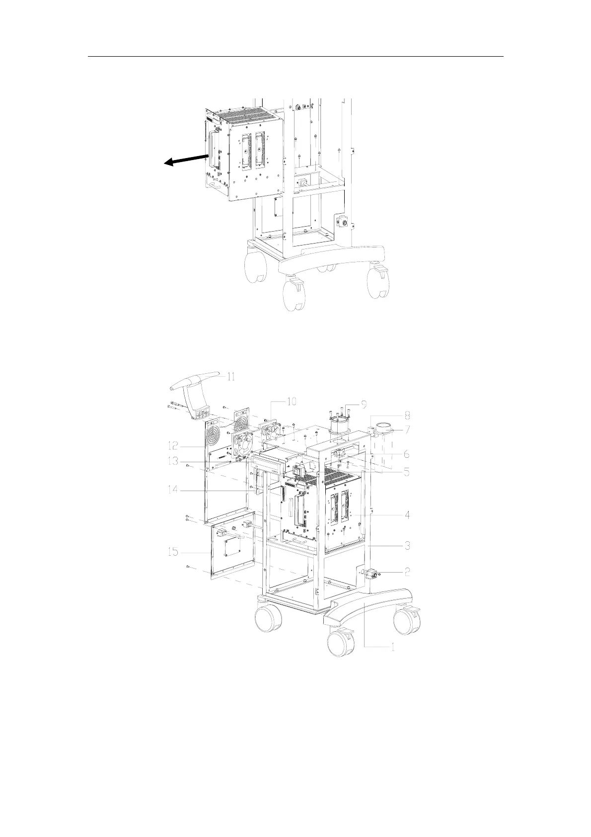
3.14. Diagram
1. Base 2. Footswitch Support 3. Framework 4. Cabinet
5. Power Switch Support 6. Shield Cover 7. Keyboard Pillar Anchor Ear
8. Transducer Cable Hanger Fixed Block 9. Keyboard Pillar Sleeve
10. Air Outlet Fan Assembly 11. Handle 12. Upper Rear Cover
13. CD-ROM 14. Hard Disk 15. Lower Rear Cover