Hardware Introduction
2-13
Connection Board
2.3.2. Working Procedure
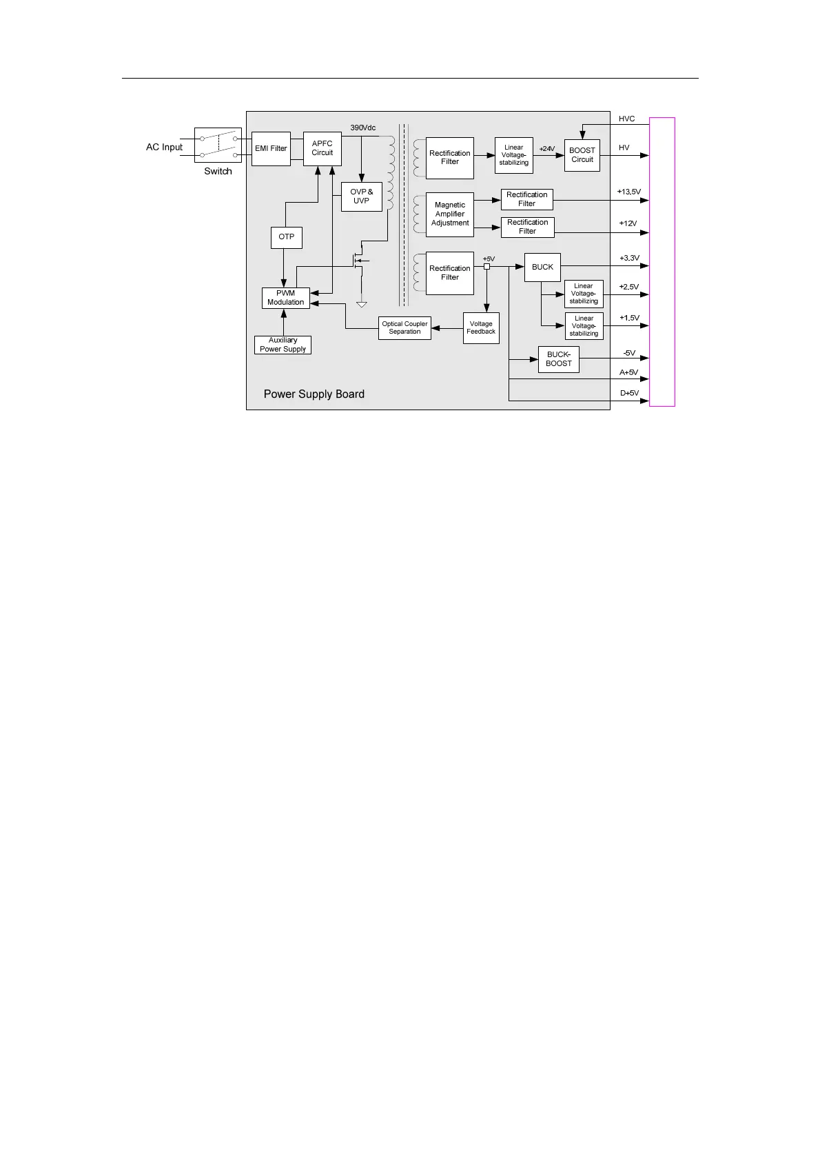
The AC input passes the EMI filter circuit and then the BOOST PFC circuit to be converted to
DC 370-410V. It then be converted to +5V, +13.5V, +12V and +24V outputs by the
two-transistor forward converter. The +5V output is the main feedback output of the converter
and others are auxiliary outputs of the converter. To obtain appropriate voltage and load
adjustment ratio, +13.5V and +12V are adjusted by the magnetic amplifier and +24V is
stabilized linearly. +5V is output directly as well as works as the input of +3.3V and -5V. +24V
is converted to the HV output by BOOST.
+5V, -5V, +13.5V and HV have the overvoltage and overcurrent protection. When the
protection takes effect for +5V, the whole power supply board stops outputting; When the
protection takes effect for -5V and HV, only -5V and HV are stopped outputting; When the
protection takes effect for +13.5V, +5V is not affected.
The power supply board also has the overtemperature protection function, which prevents
temperature of key power devices such as the transformer and MOSFET from exceeding safe
range when the system malfunctions.
2.3.3. Circuit Description
The PFC circuit uses the control chip UC3854 from TI company and BOOST converter
controlled with average current mode. It also uses IRFPC60LC (600V/16A) from IR company
as the main switch tube and ISL9RL1560G2 (600V/15A ) from FAIRCHILD company as the
follow current tube.
The control chip U8 of the FORWARD converter is the voltage control chip MB3769A from
FUJITSU company, which can adjust voltage, limit current cycle by cycle, and has built-in
functions of soft start, low-voltage lock and protection lock. The transformer T1 not only
transforms voltage but meets requirements of safe isolation. The switch tube is SPA06N60C3