– 156 –
7.
ESIGENZE DI MANUTENZIONE • MAINTENANCE REQUIREMENTS
ENGLISHITALIANO
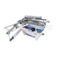
7.1.1 Cinghia di comando al-
bero pialla (fig.1)
Aprire lo sportello toupie e proce-
dere come descritto di seguito:
– Allentare i 4 dadi A di fissaggio
del supporto motore;
– Allentare la vite B di registrazio-
ne e procedere alla sostituzione
della cinghia;
– Tensionare la cinghia avvitan-
do la vite B.
A regolazione eseguita spingere il
motore tutto a sinistra contro la
battuta e stringere i dadi A e il
dado C.
Per controllare la tensione
della cinghia, adottare il
metodo indicato in figura.
Lo spostamento risultante (R)
deve essere 15 mm.
7.1.2 Cinghie trasmissione
sega e incisore
(fig.2 - fig.3)
– Smontare la lama sega e incisore
(vedi capitolo 5);
– smontare il coltello divisore C;
– smontare il convogliatrucioli D;
–abbassare completamente il
gruppo sega e inclinarlo a circa
45°.
Cinghie trasmissione sega
(fig.2)
– allentare il controdado A e la vite B;
–sostituire le 2 cinghie E e
tensionarle avvitando la vite B;
–serrare il controdado A a
regolazione eseguita;
Per controllare la tensione
della cinghia, adottare il
metodo indicato in figura.
Lo spostamento risultante (R)
deve essere 8 mm.
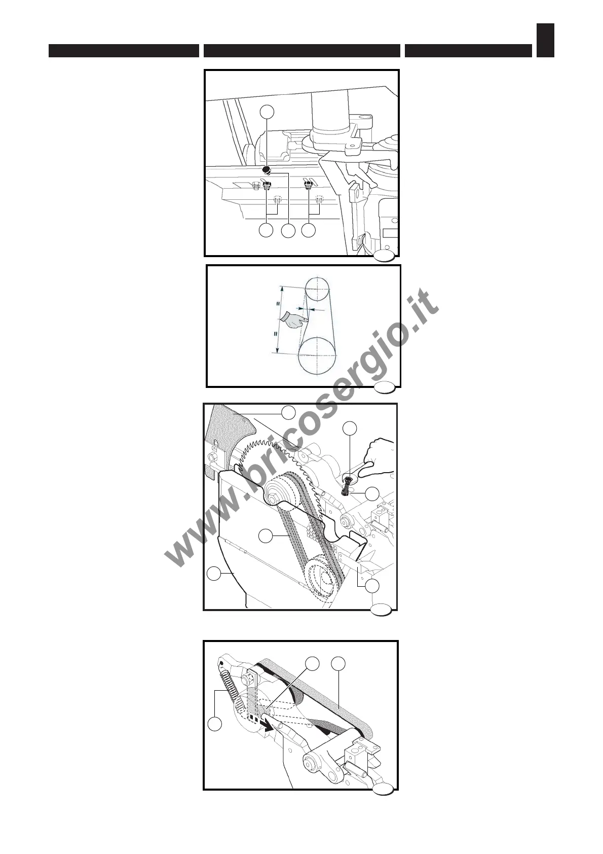
Cinghia trasmissione incisore
(fig.3)
– spingere il tendicinghia E e so-
stituire la cinghia F;
– il giusto tensionamento della cin-
ghia dell’incisore è assicurato
dalla molla G e non necessita di
alcuna registrazione.
7.1.1 Cutterblock driving belt
(fig.1)
Open the router door and proceed
as described below:
– Loosen the 4 retaining nuts A of
the motor support.
– Loosen the adjusting screw B
and replace the belt.
– Tighten the belt screwing down
the screw B.
When the adjustment has been
made, push the motor completely
to the left against the stop and
tighten the nut A and the nut C.
To check belt tension, use the
method indicated in the figure. The
resulting movement (R) must
measure a maximum of 15 mm.
7.1.2 Saw and engraver
transmission belts
(fig.2 - fig.3)
- Disassemble the saw and
engraver blades (see chapter 5);
- Disassemble the dividing knife C;
- Disassemble the shaving
conveyors D;
- Completely lower the saw
assembly and incline it to about
45°;
Saw driving belt (fig.2)
- Loosen the counternut A and the
screw B;
- Replace the belt E and tighten it
by screwing down the screw B;
- Tighten the counternut A when
the adjustment has been made;
To check belt tension, use the
method indicated in the figure.
The resulting movement (R)
must measure a maximum of
8 mm.
Engraver driving belt (Fig. 3)
- Push the belt tightener E and
replace the belt F;
- The correct engraver belt tension
is assured by the spring G and it
does not require any adjustment.
028.063.0.tif
C
B
1
A A
C
B
026_021_0.TIF
2
A
F
E
D
028.067.0.tif
G
E F
3
1a
R
2 Kg