6.
NORME DI FUNZIONAMENTO • OPERATING PROCEDURES
ENGLISHITALIANO
- 136 -
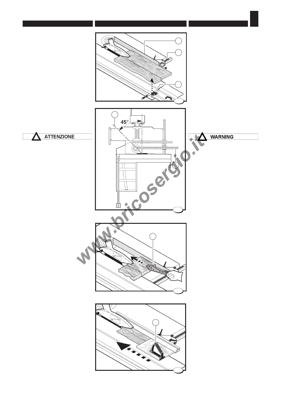
6.4.2 Lavorazione con la guida
parallela
Nell'esecuzione di tagli paralleli
usare la guida A (fig.12).
Per il suo posizionamento e rego-
lazioni seguire le istruzioni riporta-
te nel cap.5.
Posizionare il carro vagone come
in fig.12 e bloccarlo tramite il po-
mello B.
Nel posizionamento del pezzo con-
tro la guida A (fig. 12) l’operatore
fa riferimento alla scala millimetrata
C.
L'estremità della riga A (fig.13)
deve essere posizionata
longitudinalmente lungo una linea
immaginaria (B) che inizia a meta'
della lama e scivola avanti di 45°
Questo per evitare che i denti in
salita della sega afferrino il pezzo
e lo lancino contro l'operatore.
Non mettere mai le mani in
prossimità delle lame sega-
incisore; usare sempre uno
spintore.
La macchina viene fornita con lo
spintore A (fig.14) e con la mano-
pola B (fig.15).
La manopola B può essere appli-
cata a spintori di diverse dimen-
sioni avvitandola con le viti in
dotazione.
A seconda delle dimensioni del
pezzo da lavorare scegliere il tipo
di spintore più idoneo.
6.4.2 Working with the
parallel guide
To perform parallel cuts use fence
A (fig.12).
To position and adjust, follow the
instructions in chap.5.
Position the wagon as shown in
Fig.12 and lock it with the knob B.
For positioning the workpiece
against fence A (fig. 12) refer to
scale C.
The end of fence A (fig. 13) must
be positioned lengthwise along
an imaginary line (B) which starts
half way down the blade and slips
forward by 45°.
This is to prevent that when the
saw lifts, the teeth grip the piece
and launch it against the
operator.
Never put the hands near the saw
blade-engraver; always use a
pusher.
The machine is supplied with a
pusher A (Fig. 14) and with a knob
B (Fig.15).
The knob B may be applied to
pushers of different size, screw-
ing it on with the screws provided.
Depending on the dimensions of
the piece to be machined, select
the most suitable type of pusher.
A
B
7
028.056.0.tif
13
009_049_0.tif
14
A
B
7
15
009_047_0.tif
12
B
009_050_0.tif
A
C