5.
NORME DI MESSA A PUNTO • SET-UP PROCEDURES
ENGLISHITALIANO
- 94 -
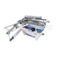
5.1.6 Engraver - assembly
(fig. 14):
– Disconnect input power.
– Lift the nut A upwards and open
the guard N; opening activates a
microswitch which prevents the
motor from starting (U.S.A. and
CANADA version).
– Insert pin B in the blade-holding
flange hole.
– Loosen lock nut C using a 13
mm hex wrench and remove
flange D.
– Assemble, by following this se-
quence, these parts: blade E
with the teeth opposed to the
ones of the saw, flange D and
nut C.
– Tighten the nut using a 13 mm
wrench and pin B.
In the U.S.A. and CANADA ver-
sion, the scoring unit is set for use
with double blade. If the simple
(single) blade is needed, position
the supplied thickness L between
flange M and the blade.
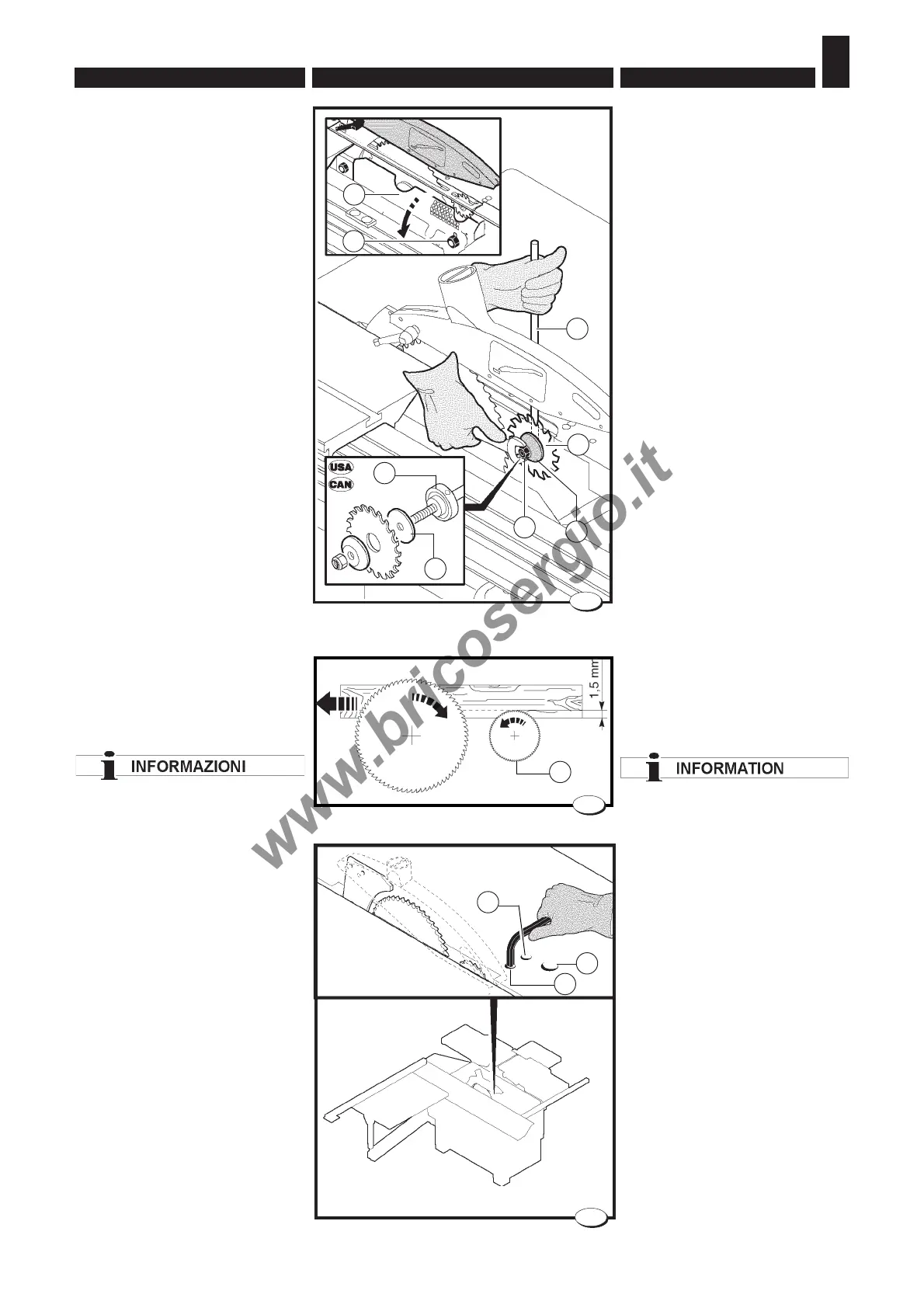
5.1.7
Scorer - adjustment
(fig. 15-16)
For cutting panels coated with
finishingmaterial you have to
use the scorer A (fig. 15);
position the scoring saw in
order to have an engraving
equal to 1-1,5 mm.
Proceed as follows if it is neces-
sary to adjust scorer positioning
with respect to the saw:
– Loosen the fastening dowel by
introducing the hex wrench into
hole M;
– Regulate the alignment of the
scoring unit with the saw by
turning the setting eccentric
through hole N;
– Adjust the height of the scorer
by introducing the hexagonal
wrench into hole L (fig. 16).
– Tighten the locking dowel M
when the adjustment is over.
5.1.6 Incisore-montaggio
(fig. 14):
– Disinserire la tensione di alimen-
tazione.
– sollevare verso l'alto il dado A e
aprire la protezione N ; l'apertura
agisce su un micro che impedi-
sce l'aviamento del motore (Ver-
sione USA e CANADA).
– Inserire il perno B nel foro della
flangia portalama.
– Allentare il dado di bloccaggio C
con chiave esagonale da 13 mm,
ed estrarre la flangia D.
– Montare in sequenza la lama E con
i denti contrapposti a quelli della
sega, la flangia D e il dado C.
– Serrare il dado con la chiave da
13 mm utilizzando il perno B.
Nella versione U.S.A. e CANADA
l'incisore viene registrato per l'uti-
lizzo con lama doppia.Nel caso in
cui si volesse utilizzare con lama
semplice (singola) è necessario po-
sizionare lo spessore L, in dota-
zione , fra la flangia M e la lama
stessa.
5.1.7
Incisore - regolazione
(fig. 15-16)
Nel taglio del pannello nobilitato è
indispensabile l’utilizzo
dell’incisore A (fig. 15) per evitare
possibili scheggiature.
L’incisore va posizionato in modo
che produca un taglio di 1-1,5 mm.
Qualora si rendesse necessario re-
golare l’incisore rispetto alla sega,
procedere nel seguente modo:
– Allentare il grano di bloccaggio
tramite chiave esagonale nel foro
M;
– Registrare l’allineamento dell’in-
cisore alla sega ruotando l'ec-
centrico di registrazione
attraverso il foro N;
– Registrare l’incisore in altezza
tramite chiave esagonale nel foro
L (fig. 16);
– Serrare il grano di bloccaggio M
a registrazione ultimata.
A
23_033_0.tif
028.035.0.tif
B
E
D
028_098_0.TIF
14
C
N
L
M
15
16
L
M
N
A