5.
NORME DI MESSA A PUNTO • SET-UP PROCEDURES
ENGLISHITALIANO
- 88 -
5.1.5 Circular saw - adjustment
5.1.5.1 Standard Version
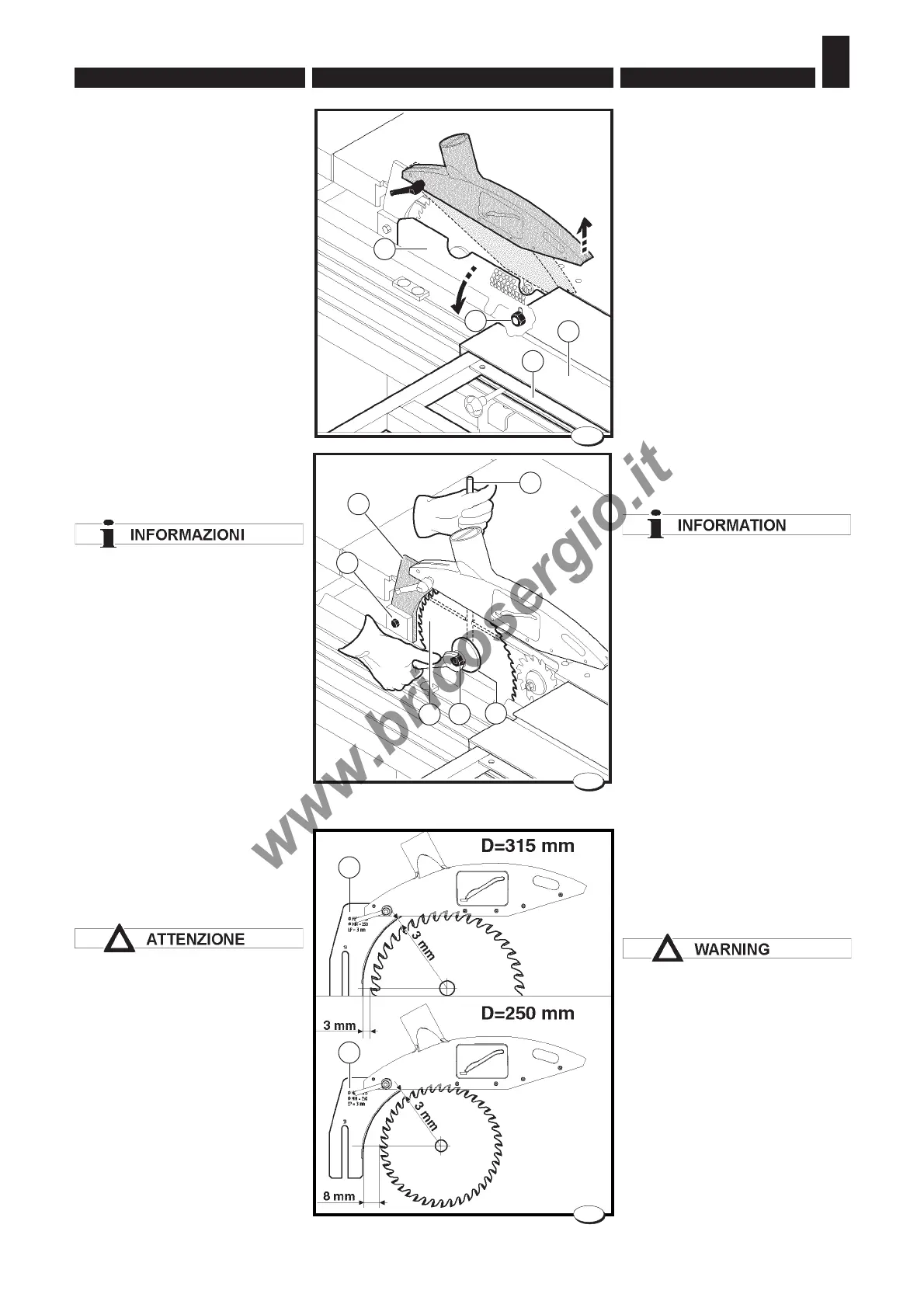
– Disconnect input power.
– Position the saw assembly at
90º and lift it as far as possible.
– Position the squaring frame A
as shown in the figure and
translate the wagon H
completely to the right.
– Lift the nut M upwards and open
the guard N; opening activates
a microswitch which prevents
the motor from starting (U.S.A.
and CANADA version).
– Fit pin B into the saw shaft pulley
hole.
The locking nut C of the saw
blade is counter-clockwise; to
unscrew it turn it clockwise.
– Loosen the lock nut C using a
24 mm hex wrench and remove
flange D.
–In sequence mount the saw E,
the flange D and the nut C (to
prevent any vibration, thoroughly
clean the flanges before mount-
ing the saw blade).
– Tighten the nut using the
24 mm wrench and the pin B.
– Adjust dividing knife F height by
unloosing nut G. (fig. 8).
The position of the dividing knife
F varies on the basis of the saw
blade diameter;
adjust its position so that its
distance from the saw blade is
between 3 and 8 mm (see
example Fig.9).
The dividing knife is in the right
position when the saw guard
covers a part of the cutting edge
of the saw blade.
5.1.5 Sega circolare
- montaggio
5.1.5.1 Versione standard
– Disinserire la tensione di alimen-
tazione.
– Posizionare il gruppo sega a 90°
e sollevarlo al massimo.
– Posizionare il telaio di squadro
A come in figura e traslare il car-
ro vagone H tutto a destra.
– sollevare verso l'alto il dado M e
aprire la protezione N; l'apertu-
ra agisce su un micro che impe-
disce l'aviamento del motore
(Versione USA e CANADA).
– Inserire il perno B nel foro della
puleggia albero sega.
Il dado di bloccaggio C della lama
sega è sinistrorso; per svitarlo
occorre ruotarlo in senso orario.
– Allentare il dado di bloccaggio C
con chiave esagonale da 24 mm,
ed estrarre la flangia D.
– Montare in sequenza la sega E,
la flangia D e il dado C (per evita-
re eventuali vibrazioni, prima di
montare la lama sega pulire ac-
curatamente le flange).
– Serrare il dado con la chiave da
24 mm utilizzando il perno B.
– Regolare la posizione in altezza
del coltello divisore F allentando
il dado G (fig. 8).
La posizione del coltello divisore
F varia in base al diametro della
lama sega; regolare la sua
posizione in modo che la sua
distanza dalla lama sega sia
compresa fra 3 e 8 mm
(vedi esempio fig.9).
Il coltello divisore è nella giusta
posizione quando la protezione
sega copre una parte del tagliente
della lama sega.
026_023_0.TIF
7
A
H
N
B
C
D
E
M
026_017_0.TIF
8
F
G
F
024_049_0.tif
9
F