4.
INSTALLAZIONE • INSTALLATION
ENGLISHITALIANO
- 60 -
4.3.5 Prolunga piano di
lavoro - Installazione
(fig. 11)
– Montare il piano A mediante le
viti B.
– Eseguire il livellamento del pia-
no agendo sui grani C.
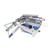
4.3.6 Gruppo fermo legno
(solo per vagone
L=2250-2600-2800)
Installazione (fig. 12)
– Allentare la maniglia A.
– Inserire il lardone C nello scavo
del vagone.
– Portare la battuta B nella posi-
zione desiderata.
– Serrare a fondo la maniglia A a
regolazione ultimata.
La conformazione del dispositivo
B consente di effettuare battute di
precisione anche di pezzi aventi
una superficie di battuta non rego-
lare.
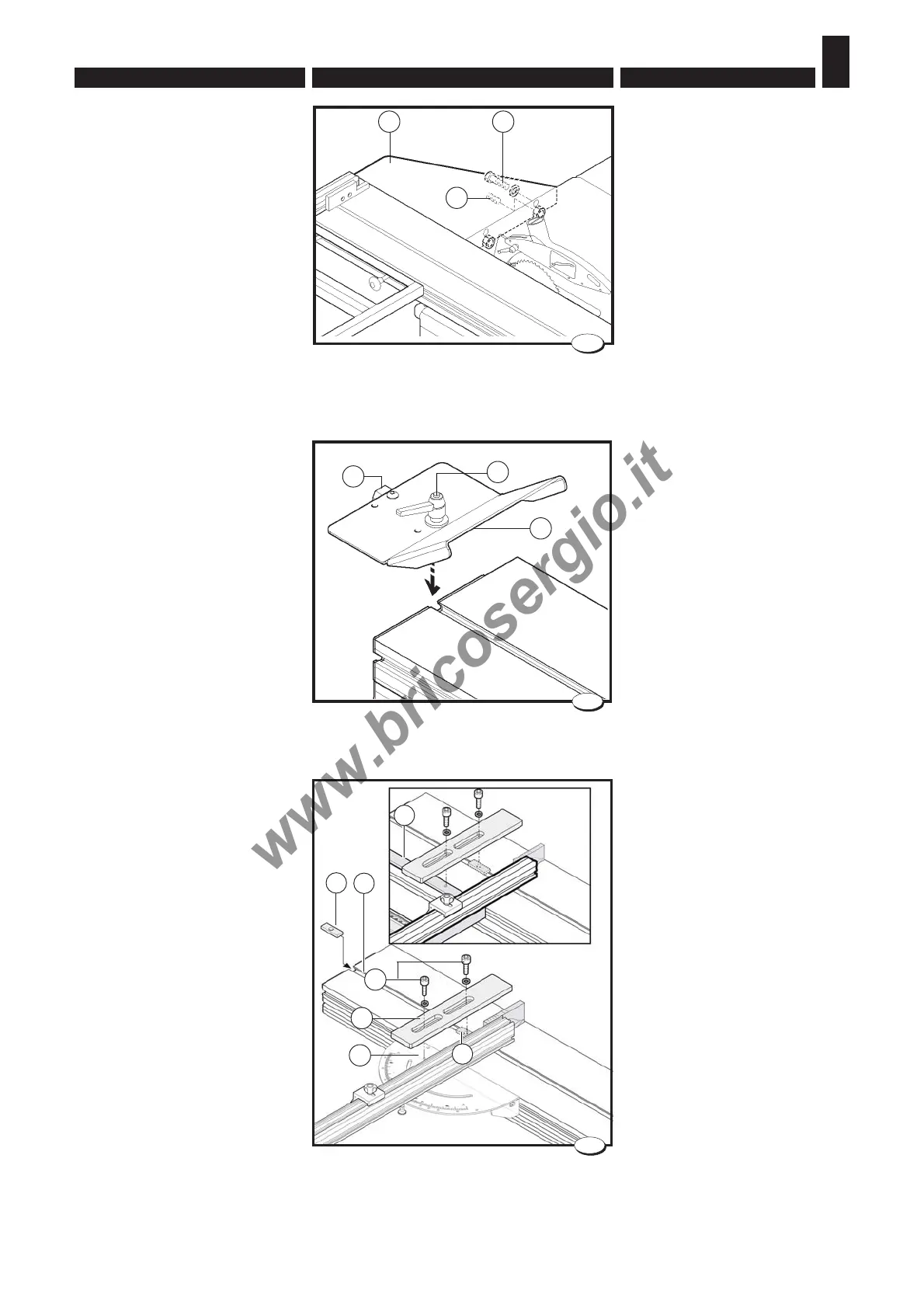
4.3.7 Pianetto a tenonare e
Protezione
Installazione (fig. 13)
– Inserire il lardone A nella scana-
latura del vagone B.
– Fissare il pianetto a tenonare C
sul piano D o F , mediante le viti
E.
4.3.5 Working table extension
- Installation (fig. 11)
– Mount the table A using the
screws B.
– Carefully level the table by
adjusting the dowel pins C.
4.3.6 Wood stop unit -
(
only whit wagon
L=2250-2600-2800)
Installation (fig. 12)
– Loosen handle A;
– Insert the gib C in the wagon
groove.
– Move stop B to the required
position;
– Tighten handle A hard after
adjustment.
The structure of device B permits
to perform precision stops also in
pieces having an irregular stop
surface.
4.3.7 Tenoning table and
Protection
Installation (fig. 13)
– Insert the gib A in the groove of
the wagon B.
– Fit the tenoning attachment C
to the table D or F by means of
the screws E.
028.012.0.tif
11
C
A B
026_014_0.tif
12
C
A
B
A
033.007.0.tif
C
D
E
B
A
13
F