4.
INSTALLAZIONE • INSTALLATION
ENGLISHITALIANO
- 66 -
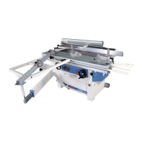
Protezione pialla (fig. 20)
– Posizionare la protezione A
come da figura.
– Avvitare la vite B di fissaggio.
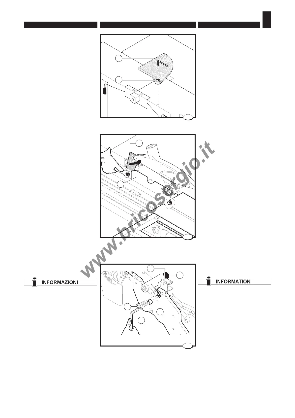
4.3.11 Gruppo incisore
- Installazione (fig. 21÷27)
Il gruppo incisore può essere ri-
chiesto anche in un secondo tem-
po.
Descriviamo quindi le operazioni
di assemblaggio da eseguire per
poterlo installare sul gruppo sega:
- togliere la lama sega seguendo
le istruzioni del paragrafo 5.1.4;
- smontare il coltello divisore N;
- togliere il convogliatrucioli sega
P svitando le tre viti che lo fissa-
no al supporto B (fig. 21-22);
- fissare il supporto incisore A al
supporto sega B;
Posizionare la molla V come
indicato in figura.
Serrare completamente le viti Z
accertandosi che le viti di registro
H siano siano perfettamente cen-
trate con i fori sul piano sega.
Planer protection (fig. 20)
– Fit the protection A into place as
shown in the picture.
– Tighten the fastening screw B.
4.3.11 Scorer assembly -
Installation (fig. 21÷27)
I
The scorer assembly may be ordered later.
We are therefore describing herebelow the
assembly operations to be executed for
scorer installation on the saw assembly:
- Remove the saw blade following the
instructions in par. 5.1.4.
-
Disassemble the dividing knife
N;
- Remove the saw wood-shaving conveyor
by unscrewing the three screws P which
fasten it to the support B (fig. 21-
22).
- Lock the scorer support A to the
saw support B;
Position the spring V as
indicated in the figure.
Fully tighten the screws Z ensuring
that the adjusting screws H are
perfectly centred on the holes on
the saw table.
028_083_0.tif
P
028.015.0.tif
21
22
N
A
B
Z
V
H
A
B
028_092_0.TIF
20