4.
INSTALLAZIONE • INSTALLATION
ENGLISHITALIANO
- 58 -
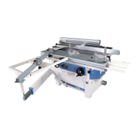
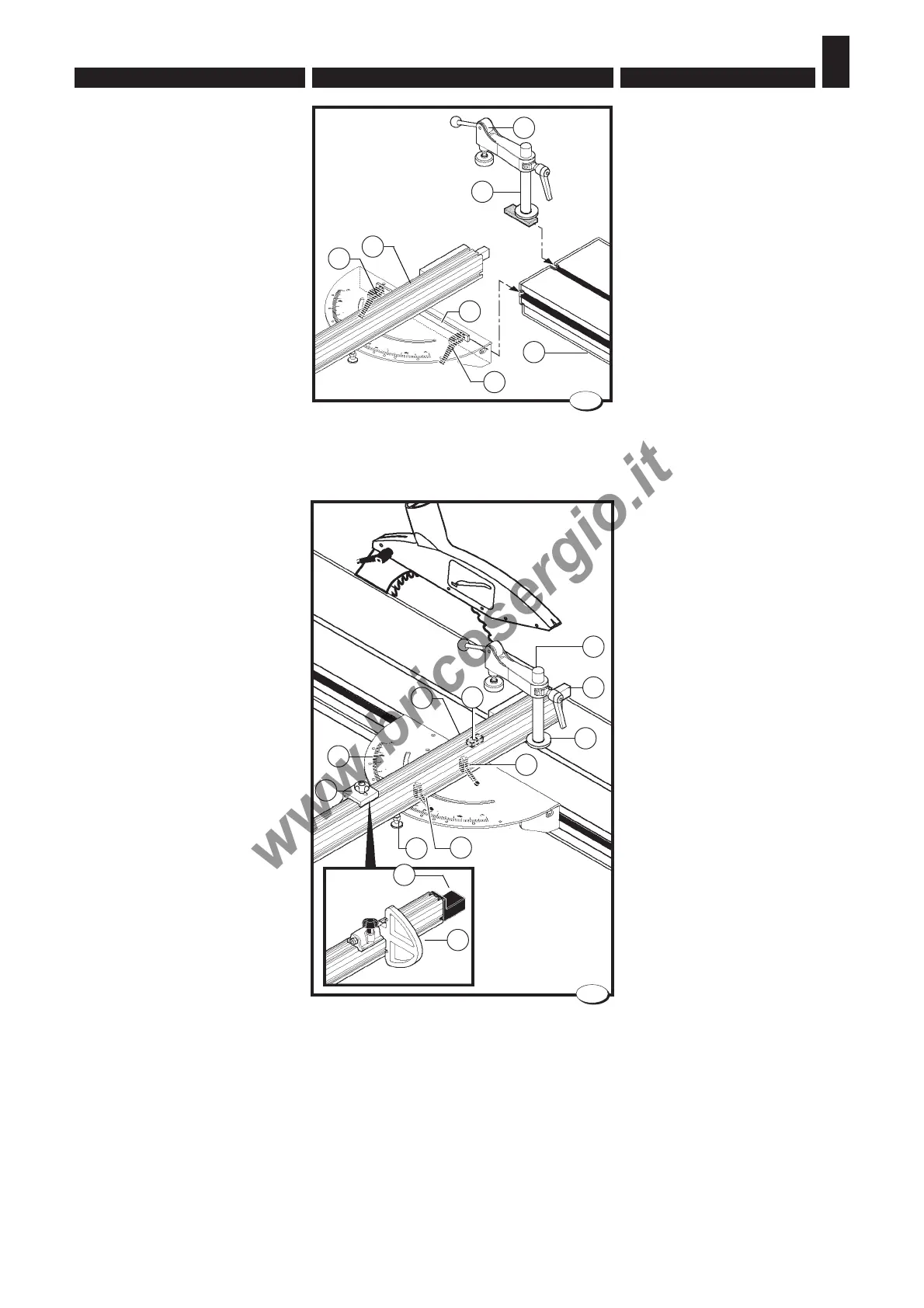
4.3.4 Angled cuts device -
Installation (fig. 9-10)
– Insert the stud bolt N with the
presser E into the groove of the
wagon C;
– Mount the ruler assembly A in-
serting the gib R in the groove of
the wagon C;
– Tighten the lever G;
– Loosen handles F and H;
– Position the ruler assembly at
the right distance from the saw
blade; at a 90
o
angle send the
ruler assembly to stop up against
the gib L; the gib L is adjusted
by our technicians and serves to
quickly position the ruler
assembly at the right distance
from the saw blade.
– To make angular cuts pull knob
R and turn the ruler assembly A
using index D as a reference;
– Block by tightening handles F and
H.
– Position the presser up against
the ruler assembly ensuring that
the washer Q is inserted into the
groove.
– Rotate the stud bolt N clockwise
to block.
On request the telescopic ruler is
supplied with the end-stops B.
These have a larger support
surface and can be positioned
quickly for bearing or thrust
machining by simply turning them
over.
When the clip guard M is worn,
bring it up against the saw blade
by turning the blocking screws.
4.3.4 Dispositivo tagli angolati
- Installazione (fig. 9-10)
– Inserire la colonnetta N con il
pressore E nella scanalatura del
carro vagone C;
– Montare il gruppo riga A inseren-
do il lardone R nella scanalatura
del vagone C;
– Serrare le leve G;
– Allentare le maniglie F ed H;
– Posizionare il gruppo riga alla giu-
sta distanza dalla lama sega;
nella posizione a 90° mandare il
gruppo riga in battuta contro il
lardone L; il lardone L è registra-
to dai nostri tecnici, e serve per
posizionare velocemente il grup-
po riga alla giusta distanza dal-
la lama sega .
– Per l'esecuzione di tagli angolati
tirare il perno R e ruotare il grup-
po riga A facendo riferimento alla
scala D;
– Bloccare serrando le maniglie F
ed H.
– Posizionare il pressore contro il
gruppo riga accertandosi che la
rosetta Q si inserisca nella sca-
nalatura;
– Ruotare la colonnetta N in senso
orario per bloccarla.
Su richiesta la riga telescopica vie-
ne fornita con le battute B.Queste
hanno una superficie d'appoggio
maggiore e si possono velocemen-
te posizionare per lavorazioni in ap-
poggio o in spinta semplicemente
ribaltandole.
Quando il paraschegge M si usu-
ra, avvicinarlo alla lama sega agen-
do sulle viti di bloccaggio.
033_005_0.TIF
10
033.004.0.tif
9
A
R
N
C
G
G
E
F
H
R
A
D
L
B
P
Q
N
M
M