4.
INSTALLAZIONE • INSTALLATION
ENGLISHITALIANO
- 56 -
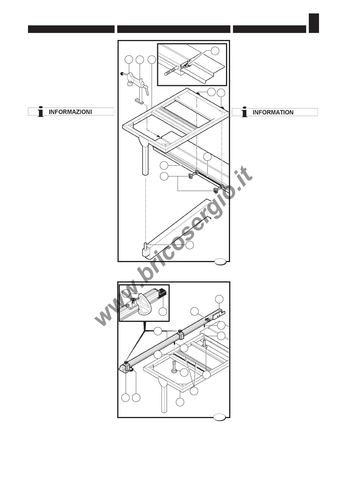
4.3.2. Square up frame
Installation (fig. 7)
– Insert the support B in the groove
of the wagon A.
–Place the frame C on the support
B and on the pin D, and insert the
two pads H in the wagon groove.
The screw D must sit perfectly
in the special hole underneath
the frame C.
If necessary, level the table C by
acting on the pin D.
–Tighten the knobs E.
– Insert the stud bolt L with the
presser M in the groove of the
wagon A and turn it clockwise to
lock it.
– When the wagon A is not used,
lock it with the lever N.
4.3.3 Telescopic ruler -
Installation (fig. 8)
–Place the telescopic ruler on the
frame, inserting the fulcrum C in
the hole R and the fulcrum S in
the slot T.
–Position the telescopic ruler in
such a way that the pin C fits into
place against the gib L. The gib L
is adjusted by our technicians and
is used to rapidly position the tel-
escopic ruler at the right distance
from the saw blade (only at a 90°
position).
–For use, position the ruler
referring to the plate P and tighten
the knobs F and E.
The ruler is fitted with an extractable
telescopic extension H, which may
be lengthened as required after
loosening the knob G.
When the clip guard M is worn, bring
it up against the saw blade by
turning the blocking screws.
On request the telescopic ruler is
supplied with the end-stops B.
These have a larger support
surface and can be positioned
quickly for bearing or thrust
machining by simply turning them
over.
4.3.2 Telaio di squadro -
installazione (fig.7)
– Inserire il supporto B nella sca-
nalatura del carro vagone A.
– Appoggiare il telaio C sul sup-
porto B e sul perno D, e inserire
i due pattini H nella scanalatura
del vagone.
La vite D deve alloggiare
perfettamente nell'apposito foro
presente sotto al telaio C.
Se necessario livellare il piano
C, agendo sul perno D.
– Serrare i pomelli E.
– Inserire la colonnetta L con il
pressore M nella scanalatura del
carro vagone A e ruotarla in sen-
so orario per bloccarla.
– Quando non si utilizza il vagone
A bloccarlo con il pomello N.
4.3.3 Riga telescopica -
Installazione (fig. 8)
– Appoggiare la riga telescopica sul
telaio inserendo il fulcro C nel foro
R e il fulcro S nell’asola T.
– Posizionare la riga telescopica
in modo da mandare il perno C
in battuta contro il lardone L; il
lardone L è registrato dai nostri
tecnici, e serve per posizionare
velocemente la riga telescopica
alla giusta distanza dalla lama
sega (solo nella posizione a 90°).
– Per l'uso posizionare la riga fa-
cendo riferimento alla targhetta
P, e serrare i pomelli F ed E.
La riga è dotata di una estensione
estraibile a canocchiale H la quale
se necessita si può allungare dopo
aver allentato il pomello G.
Quando il paraschegge M si usu-
ra, avvicinarlo alla lama sega agen-
do sulle viti di bloccaggio.
Su richiesta la riga telescopica vie-
ne fornita con le battute B.Queste
hanno una superficie d'appoggio
maggiore e si possono velocemen-
te posizionare per lavorazioni in
appoggio o in spinta semplicemen-
te ribaltandole.
028.008.1.tif
B
D
H
H
E
C
M
L
7
N
028.026.1.tif
8
H
C
E
S
D
R
F
P
T
M
L
G
A
B
A
M