4.
INSTALLAZIONE • INSTALLATION
ENGLISHITALIANO
- 54 -
4.3. INSTALLAZIONE PARTI
SMONTATE -
PREMESSA
Togliere le staffe C (fig. 3) che
bloccano i piani a filo per le
operazioni di trasporto.
Alcuni elementi risulteranno smon-
tati dalla struttura principale della
macchina, per esigenze di imbal-
laggio e trasporto.
Procedere alla loro installazione
come descritto di seguito.
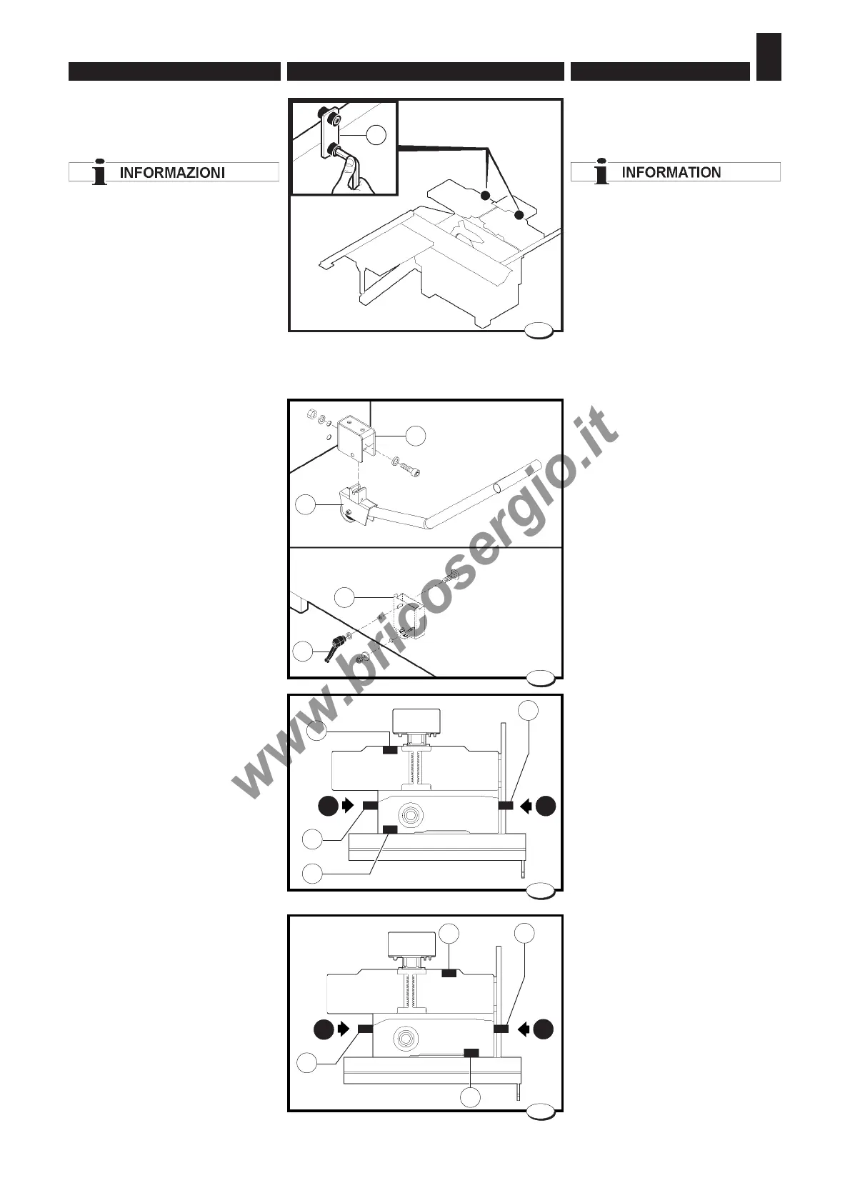
4.3.1. Ruote di spostamento -
Montaggio
Il gruppo ruote è composto da
(fig.4):
– 2 ruote fisse (A)
– 2 supporti (B)
– 1 ruota mobile (D).
Per il montaggio e l'utilizzo delle
ruote fare riferimento alla fig.5 per
la versione con toupie fissa e fig.6
per la versione con toupie
inclinabile.
– Smontare il carter pannello elet-
trico e il carter lato spessore
(solo nella versione con TOUPIE
INCLINABILE).
– montare le ruote fisse A e i sup-
porti B.
Per l'utilizzo delle ruote procedere
in questo modo:
– inserire l'attrezzo D nel suppor-
to B dal lato 1 e utilizzarlo come
leva per il sollevamento della
macchina;
– abbassare le ruote fisse A e
serrarle mediante le maniglie C;
– spostare l'attrezzo D dalla parte
opposta della macchina (lato 2),
inserirlo nell'attacco B e proce-
dere alla movimentazione della
macchina.
4.3. INSTALLATION OF
DISASSEMBLED PARTS
- INTRODUCTION
Remove the bracket C (fig. 3)
fastening the surface tables
during transport operations.
A few machine elements will be
disassembled from the machine
main structure due to packaging
and shipping requirements.
These loose parts should be in-
stalled as follows.
4.3.1 Displacing wheels -
Assembly
The unit is composed by (fig. 4):
– 2 fixed wheels A
– 2 mounts B
– 1 caster wheel D
For assembly and use of the
wheels, refer to Fig. 5 for the fixed
router version and Fig. 6 for the
inclinable router version.
– Disassemble the electric panel
cover and the cover on the shim
side (only for the version with
INCLINABLE ROUTER).
– mount the fixed wheels A and
the supports B.
To use the wheels, proceed as
follows:
– fit the jack D into the support B
from the side 1 and use it as a
lever to lift the machine;
– lower the fixed wheels A and
tighten them by the handles C;
– push the jack D toward the
opposite side of the machine
(side 2). Attach it to the mount B
and then start moving the
machine.
028.024.0.tif
3
C
028.075.0.tif
5
028.076.0.tif
6
028.045.0.tif
4
A
B
D
B
A
A
A
B
A
1
1 2
2
B
C
B