1174-00
PLOTDATUM : B-Stand : 003 / Ri. / 19.12.07 [004 / kupe / 19.12.07]19.12.2007
-X25
-X1
97098511
-W11
-X26
-G2
-G2.X3:-G2.X2:-G2.X4:
-G2.X1:
-G1
97096986
-W1
-X24
97094346
-W8
-X18
-M7
-K1
-X19
99-7036-50
97094346
-W8
-Y1
-X102
-X101
-S11
97099063
-W9
97094304
-W6
97101547
-W3
-X31
97096721
-W12 (option spray tool)
-A1
-A1.X9:
-A1.X8:
-A1.X21: -A1.X34:
-A1.X20:
-A1.X4:
-A1.X22:
-A1.X1: -A1.X2:
-A1.X11:
connected (state of deliver):
battery type Gis (wet)
disconnected:
battery type GiV (dry)
-S1
-A2
-A2.X1:
-A2.X7:
-A2.X5: -A2.X6:
-S7
97096994
-W2
-S5
-A3
-S6
97099071
-W16
-M3
-M4
-M3.S1
θ
-M4.S1
θ
-X12
-X32
97097786
-W14
-R1
-S4
notice:
-M1
-X8
-M2
-X10
97098503
-W13
-M1.S1
θ
-S3
-X9
97101547
-W3
2
1
4
3
Blatt:Blattzahl:Normgepr.
Datum Name
Gezeichnet
Geprüft
NameDatumÄnd.-Nr.Nr.
VES-Nr. :
Ersatz für :
Änd. Nr. :
Benennung
Typ:
Zeichnungs-Nr.
Hako-Werke GmbH
D-23840 Bad Oldesloe
31
Gl.Nr.
1066-00
07.06. kupe19.12.07 Ri.
2007
2 ./.
A1
-A1.X9:5
-K1:1 -G1:P(+)
P
35mm²
-K1:3 -G1:N(-)
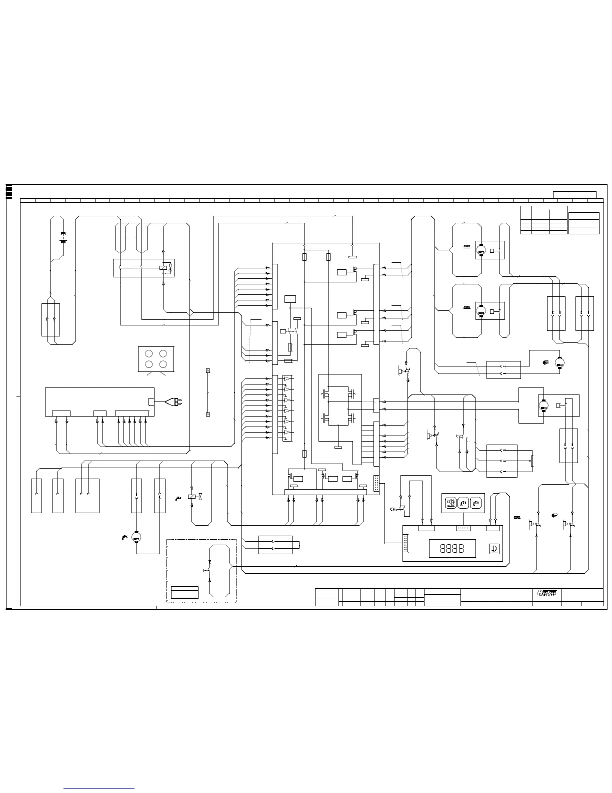
on-board-charger
supply main
1 2 12 123456
-K1:1
4mm²
N
-A1.X9:12
-X1:PB
P(+)
N(-)
-X1:NB
-K1:3
4mm²
35mm²
1
-A1.X11:1
2
-A1.X11:6
-A1.X21:1
-A1.X21:2
0,75mm²
-A1.X8:2
-A1.X21:5
-X1:PS-A1.X1:
-A1.X21:7
4mm²
-G2.X4:1
-A1.X21:4
-A1.X21:6
0,75mm²
-A1.X8:4-A1.X11:4-M7:RD
water
pump
RD
BK
-A1.X21:8
-X1:NS
4
3A1
A2
1
2
-A1.X2:
-A1.X21:3
4mm²
-G2.X4:2
-A1.X11:9-M7:BK
0,75mm²
-A1.X8:3-A1.X8:1
35mm²
35mm²
0,75mm²
water valve
option
spray tool
-A1.X11:3
1
2
-A1.X11:8
virtual ground
at direction switch
-X101:
1mm²
-X102:
virtual ground
at chassis
-A2.X6:1
spray tool on
-A2.X6:2
0,75mm²
0,5mm²
0,5mm²
0,75mm²
-G2.X3:6
-G2.X3:5
-G2.X3:4
-G2.X3:3
-G2.X3:2
-G2.X3:1
-G2.X2:2
-G2.X2:1
-K1:A1
-K1:A2
-K1:1
-K1:3
-X8:1B
-X9:2B
-X10:1B
-X10:2B
-S3:1
-S3:2
-S4:1
-S4:2
-X25:B
-X26:B
-X31:1B
-X31:2B
-A1.X9:6
-A1.X9:13
1
2
-X31:2S
-X31:1S
35mm²
-Y1:1
-Y1:2
0,5mm²
-K1:2
controller
3
10
4
11
1
8
2
9
5
12
6
13
F1
125A
2
4
3
1
1
2
5
7
4
6
8
3 1
2
3
4
5
6
1
2
1
2
3
4
5
6
7
8
F2
50A
LOGIC
F6
10A
F5
2A
LOGIC
LOGIC
LOGIC
38 49 16510
LOGIC LOGIC
27
7
14
LOGIC
VCC2
F3 5A
-X18:S
-X19:B
35mm²
0,5mm²
-K1:4
-X24:1B
-X24:2B
-M3:1
-M3:2
-M4:1
-M4:2
-X12:1B
-X12:2B
-M1:BK
-M1:RD
-S5:NO
-S6:3
-S6:1
-X32:3B
-S7:C
-X32:2B
6mm²
6mm²
2,5mm²
-A2.X5:1
key
switch
BAT
control
panel
21 12
-X32:1B
dead man
switch right
C
NO NC
-A1X4:6
-A2.X5:2
-S1:
-S1:BAT
-A1.X4:1
dead man
switch left
C
NO NC
-S6:2
key
board
-A1.X4:3
6mm²
6mm²
6mm²
6mm²
-S5:C
2
13
direction
switch
+
-
2,5mm²
-A1.X4:4
brush-
motor
left
brush-
motor
right
0,5mm²
0 1
-A1.X34:1-A1.X34:2-A1.X34:3-A1.X34:4
-S11:
-S11:
-X8:1S-X8:2S-X9:1S-X9:2S
-A1.X34:5
-A1.X34:6
-S7:NO
-A1.X4:5
-A1.X4:7
1
2
1
3
2
-M2:GY
-M2:BK
-R1:
-R1:
-R1
+
-
drive
motor
speed giver
-A1.X9:11
0,75mm²
-A1.X9:4
brush
on
1
24
loom of cables -W13 (97098503) and loom of
cables -W14 (97097786) only for cylindrical
scrub brush. For conical brush connect the wires
of thermal switches direct at -X8 and -X9.
0,75mm²
BK
RD
1
-M3.S1:-A1.X9:1
suction motor
2
-M3.S1:-X9:1B
GY
BK
1
-M1.S1:-A1.X9:2
2
-A1.X9:10
-M1.S1:-A1.X9:9-A1.X9:3
suction
on
1
24
1
-M4.S1:-X8:2B
2
-M4.S1:-A1.X9:7
0,5mm²
connection conical brush
at motor -M3/4
binder plug topside
connection N
binder plug below
connection P
-M3:1
-M3:2
conical brushmarking
cylindrical
-M3:N
-M3:P
motor connection
cable
-M3:N
-M3:P
-M4:1
-M4:2
-M4:P
-M4:N
-M4:N
-M4:P
scrub brush
91026567
91026567
=
+
wiring diagram E2833
M
-
-
-
-
-
-
-
-
-
connector -X31
M
M
M
M
topview -K1
Für diese Zeichnung behalten wir uns alle Rechte vor.(Gemäß DIN 34) 7062-12/15/18
1 2 3 4 5 6 7 8 9 1011121314151617181920212223242526272829303132333435363738 39
Zahl kommt vor
0,1
0