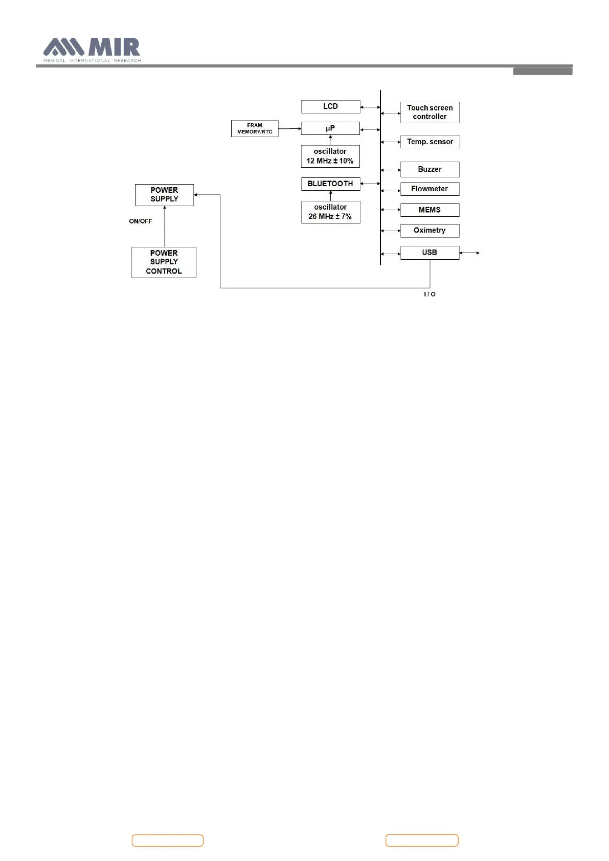
2.1. MAINBOARD MODULE
The mainboard module translates the input signal from the turbine flowmeter into spirometry values and compares them
with the predicted values calculated with the parameters age, sex, height, weight and ethnic group. Test results are
displayed on a LCD and can be printed on paper with an external printer. Spirometry test data are stored into memory and
are available for later use.
The mainboard module also makes a calculation using the oximetry input signal; from this signal collected at a 16
msec/frequency the percentage value of oxygen saturation in the blood and the heart beat values are obtained, which are
oximetry parameters.
The mainboard module includes:
- Main Microcontroller
- FLASH memory with device configuration and spirometry data
- FRAM IC with non volatile memory and real time clock
- Measuring controller for flow, volume and ambient temperature
- Ambient temperature sensor (to enable conversion from ATP to BTPS conditions).
- USB port
- Oximetry port
- Bluetooth module
2.1.1. Charging controller for battery pack (IC7 LTC 4067)
The charging controlling circuit used in the Spirodoc ensures a charge and optimum condition of the battery pack
providing that the battery temperature and voltage are within the preset limits. Temperature, voltage and time are all
monitored throughout the charge process.
The charging process itself is automatically initiated in two situations:
1. After connecting the battery charger to the unit.
2. When the unit is switched on, the battery charger is connected and the voltage level of the battery is below a preset
limit. In this situation the LCD indicates the low battery status with one line in the battery indicator.
The fast charging process is terminated by any of the following:
- Battery voltage out of range (Maximum/Minimum)
- Battery temperature out of range (Maximum/Minimum)
- Maximum charging time (timeout = 2h after the voltage arrives at the maximum value, 4.2 V)
Charging phases: