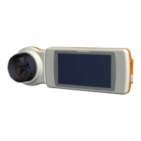
4.3. PCBs and components
4.3.1. Removing and replacing the display
Open spirodoc as described in Paragraph 4.2.1; once the
PCB is separated from the upper casing, remove the
reinforcement sheet and the damaged display from the
upper casing.
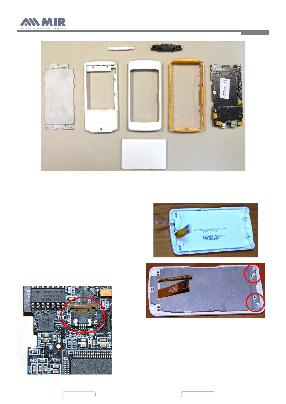
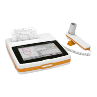
Then apply a new display in the correct position on the
upper casing; apply again the reinforcement sheet. The
position of this element is mandatory so check the correct
housing as indicated in the image alongside.
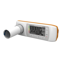
Connect the two flat cables of the display to the PCB. First
apply the square connector to CON 12: apply pressure with
one finger until a click is heard; then apply the other
connector to CON 2. After the connector is inserted then
close the brown wings to block the connector.
Do not apply an excessive bend to the flats of the display
near to the connecter, as this could cause breakage or
malfunction. The picture below shows an excessive
bending: