- turbine
Electrical parts:
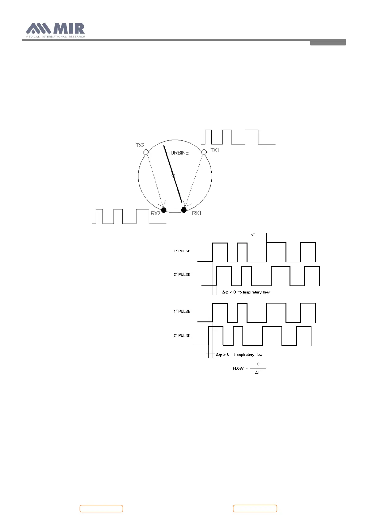
- Two pairs of infrared transmitters/receivers positioned as shown below.
- A signal conditioning circuit to rectify the output signal from the two infrared light receivers.
The rotation of the rotor causes the interruption of the infrared beam, thus creating a pulse signal which has a frequency
directly proportional to the flow.
The measurement of the air flow which passes through the tube is therefore proportional to the number of interruptions
of the infrared beam.
The phase difference (positive or negative)
between the signals from each of the two infrared
receivers (RX1 and RX2) depends upon the direction
of rotation of the moving rotor and therefore supply
the information of the direction of the air flow
(expiration or inspiration).
In detail, > 0 for expiratory flow, < 0 for
inspiratory flow.
The two pulse trains are squared by a Schmitt trigger
(LMV932MM on MiniFlowmeter) and then sent to
two input ports of the microprocessor (IC17
CP3BT26, pins 38 and 36).
The main microprocessor has the possibility to switch
all the peripheral ports on or off, including the
turbine.
3. MAINTENANCE
3.1. GENERAL
We recommend checking the spirodoc on an annual basis.
For cleaning of the spirodoc
and the accessories please see the User Manual.
3.2. TEST EQUIPMENT
For the repair and maintenance procedures of the spirodoc the following test equipment and accessories are required:
- Complete set of precision engineering tools (including 2.5 mm allen key and cross-screwdriver)
- Calibration syringe (3L is recommended)
- Case opener