FA-200 Series Installation and Operation Manual
5
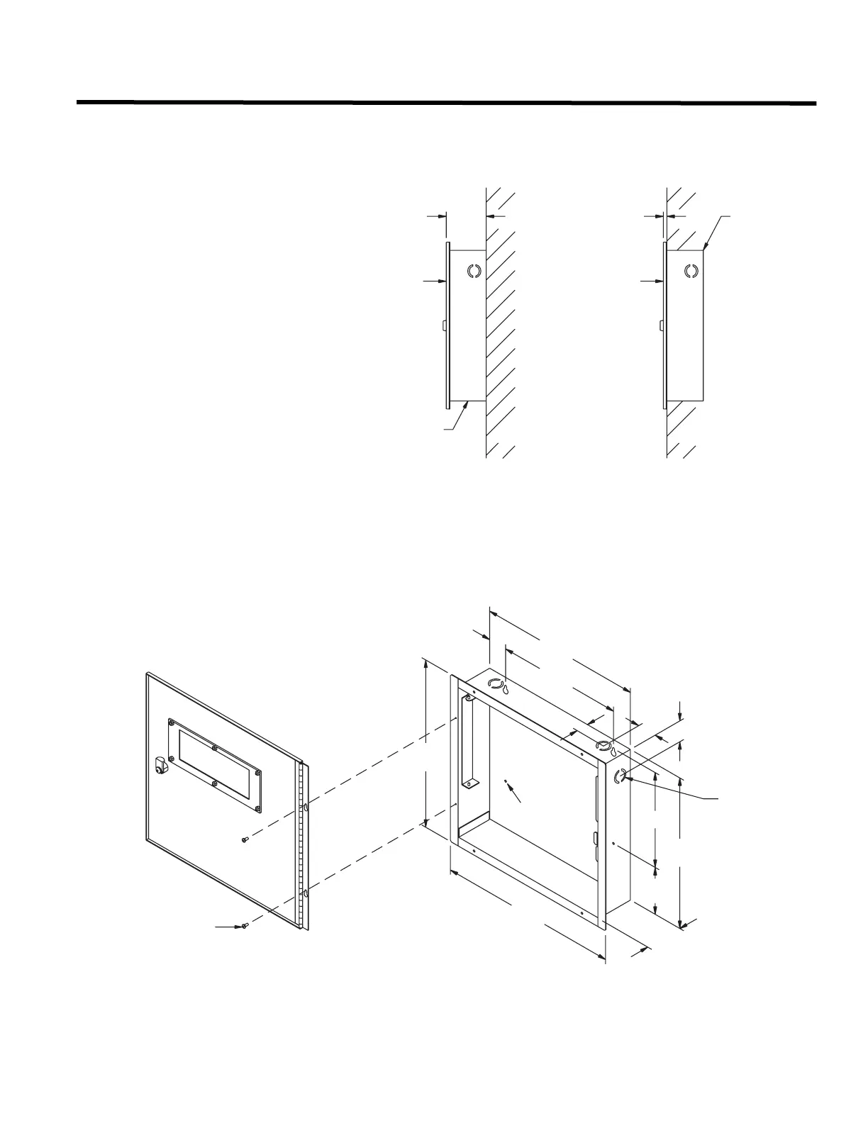
Mechanical Installation and Dimensions
Install the enclosure as shown in Figure 1, below for the FA-201, FA-202, or FA-204.
Figure 1: FA-201, 202, and 204 Enclosure Installation and Dimensions
DOOR
BACKBOX
WALL
(SIDE VIEW)
SURFACE
DOOR
8
3
"
3
-
BACKBOX
DIA.
WALL
(SIDE VIEW)
FLUSH
BACKBOX
DOOR
-
16
5
"
13
4
3
-
"
"
-
5
8
1
1
-
"
2
10
7
-
"
32
HOLE
12
4
3
-
"
8
7
-
"
8
"
-
15
8
1
"
-
8
1
"
14
1
-
8
3
"
-
3
3
1
"
4
1
"
#6 x 5/16" SCREW
KNOCKOUT
-
8
7
"
&
"
1
8
-
1
1
5
8
-
"
FINISH: PAINTED
MATERIAL: 18GA (0.048") THICK
COLD ROLLED STEEL