FA-200 Series Installation and Operation Manual
17
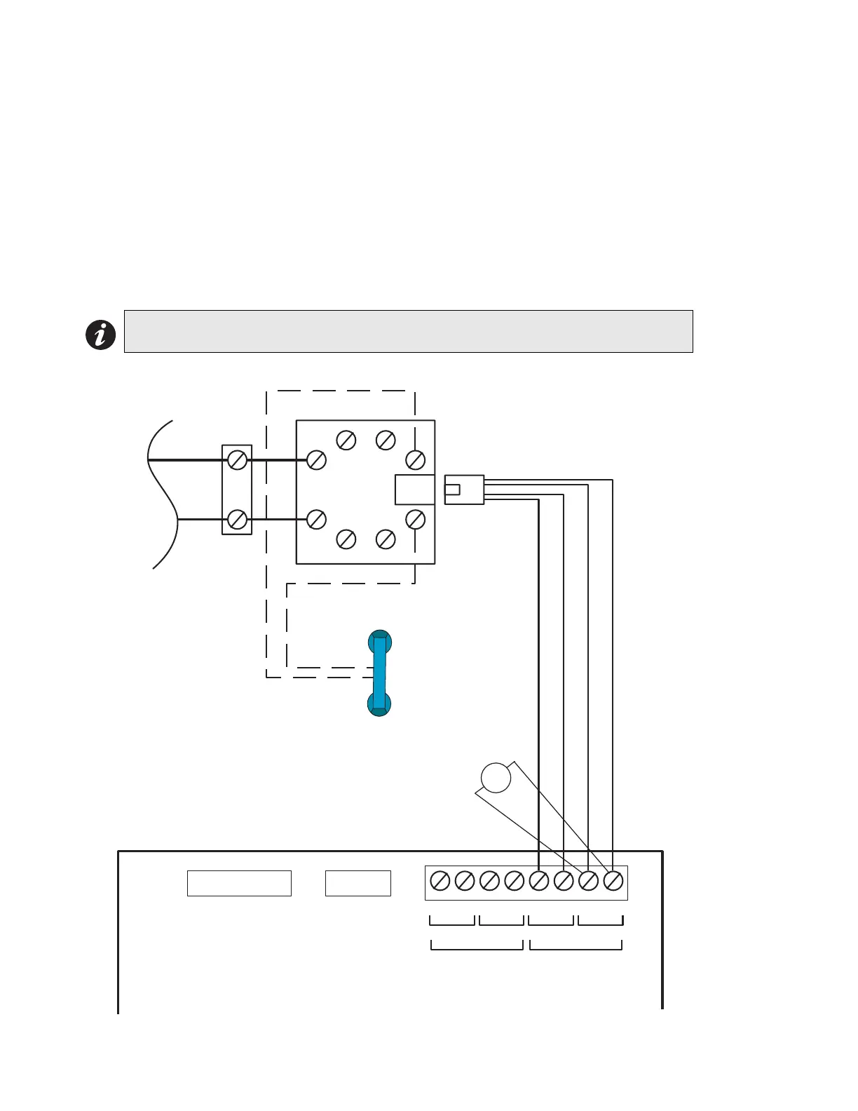
DACT / Dialler Module (DACT-100A) Terminal Connections
The following diagram shows the wiring connection for the DACT-100A, refer to the Manual for more details.
Wire the two telephone lines devices to terminals as shown in Figure 14 below.
Line 1 Input (Tip/Ring): To the first Telephone Line via the required RJ31X Connector.
Line 1 Output (Tip/Ring): To an optional Premise Telephone on the first Telephone Line via the required RJ31X
Connector.
Line 2 Input (Tip/Ring): To the second Telephone Line via the required RJ31X Connector.
Line 3 Output (Tip/Ring): To an optional Premise Telephone on the second Telephone Line via the required RJ31X
Connector.
Note that most AHJs do not allow the connection of premise telephones. See Wiring Tables on page 20and
Appendix C page 38 for more information.
Figure 14: DACT-100A Wiring Diagram
Note: The terminal blocks are “depluggable” for ease of wiring.
P1 FOR
CONNECT
TO FIRE
ALARM
PANEL
P2 FOR RS-485
I/F TO PC
LINE-1
TIP / RING TIP / RING TIP / RING
DACT-100A MAIN BOARD
IN OUT INOUT
LINE-2
RING / TIP
PREMISE PHONE
(IF PERMITTED)
TO
ELEPHONE
COMPANY
WIRING
BROWN
GRAY
GREEN
RED
TIP
RING
RJ31X
4
3
2
1
5
6
7
8
V
RED
BLACK
-
+
VOLTAGE
MEASURED
SHOULD BE
APPROX. 40V
Alantic
Scientific
Model
#24544
Protective
Device or
similar UL
Listed
QVRG
Secondary
Protector
PROTECTOR
BLOCK