FA-200 Series Installation and Operation Manual
7
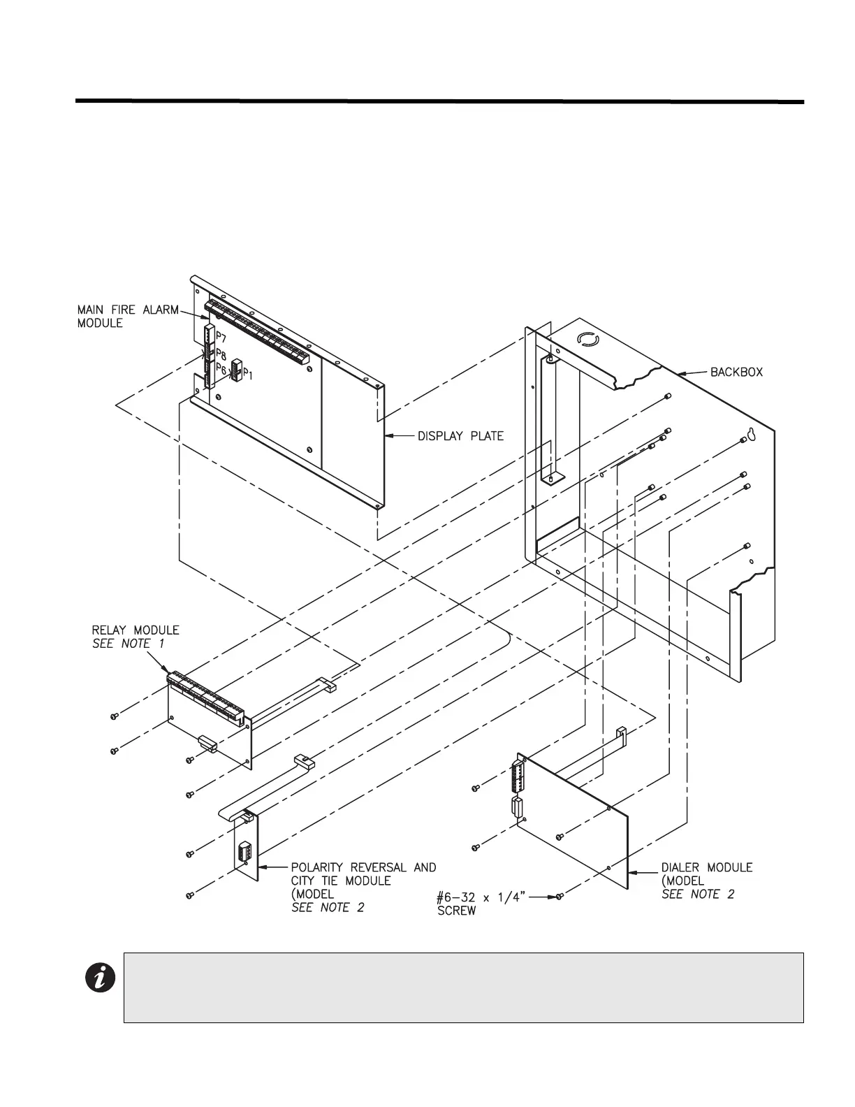
Modules Mounting Locations
The FA-200 eries come pre-assembled with all components and boards, except for adder modules. Module
installation locations are shown below.
Be sure to connect a solid Earth Ground (from building system ground / to a cold water pipe) to the Chassis Earth
Ground Mounting Lug, and to connect the Earth Ground Wire Lugs from the Main Chassis to the ground screw on
the backbox.
Figure 3: FA-201, 202, and 204 Module Mounting Locations
Notes:
1. Relay module may be model RM-204 or RM-208.
2. Only one of PR-100 or DACT-100A may be installed.
PR-100)
DACT-100A)