Module Settings
10
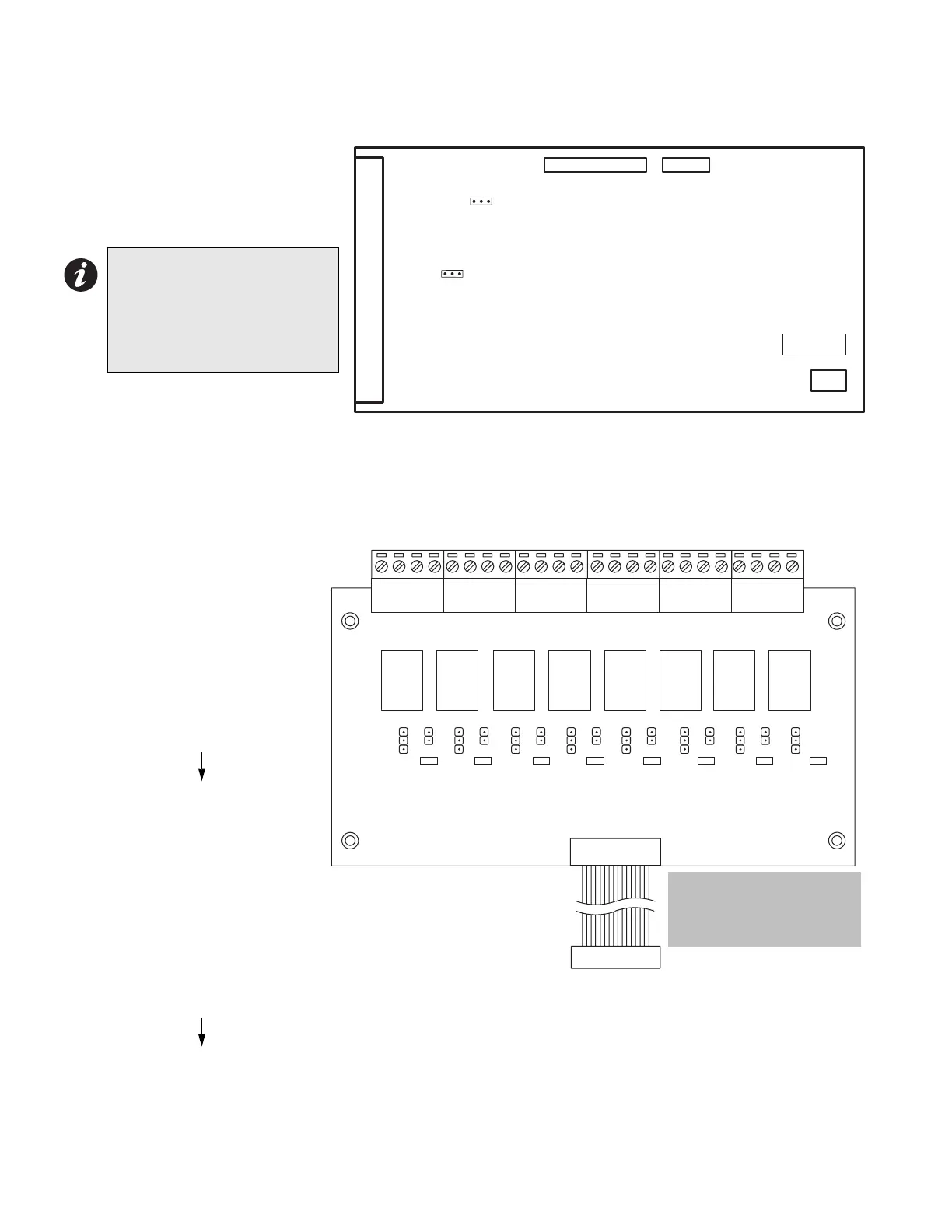
Zone Adder Module (Model DM-204)
Figure 6: DM-204 Zone Adder Module
Class A / B Selection: JW2 & JW3
are connected from 1 to 2 for initiating
circuit Class B (Style B) operation,
and from 2 to 3 for Class A (Style D)
operation.
P1 & P2: Connections to P7 & P6
respectively on the main fire alarm
board.
SW5,6: Config DIP switches.
Relay Modules (Models RM-204 or RM-208)
Figure 7: RM-204 or RM-208 Relay Adder Module
P1: Connect to P1 on the main fire
alarm board.
By the factory setting, the four or
eight relays are controlled by
initiating circuits 1 to 8
respectively. This is configured by
selecting:
• JW1: Initiating Circuit #1
controls Relay #1.
• JW2: Initiating Circuit #2
controls Relay #2.
• JW8: Initiating Circuit #8
controls
Relay #8.
Alternately, each relay may be set
as a Common Alarm or Common
Supervisory Relay by removing
the jumper from JW1 to JW1A,
etc. These jumpers have two
positions to select Alarm or
Supervisory each.
• JW1A: Alarm or supervisory control for Relay #1.
• JW2A: Alarm or supervisory control for Relay #2.
• JW8A: Alarm or supervisory control for Relay #8.
Finally, there are jumpers JW1.2, JW2.3, up to JW7.8 that allow a relay to have the same control as an adjacent
relay. For example, starting with the factory default setting, moving the jumper from JW2 to JW1.2 will make both
relays 1 & 2 operate with Initiating Circuit #1.Contact Mircom Technical Support for assistance if required.
Note: The Class A/B
selection affects all
initiating circuits, and
must be used with the
correct Configuration
DIP switch setting.
P1
FIELD WIRING TERMINALS
P2
SW5
231
JW3
SW6
231
JW2
ALM
K1
RLY1
RM-208/RM-204
RELAY MODULE
RLY2 RLY3 RLY4 RLY5 RLY6 RLY7 RLY8
NO
NO
NC
COM
NO
NC
COM
NO
NC
COM
COM
NO
NC
COM
NO
NC
COM
NO
NC
NC
COM
NO
NC
COM
K2 K3 K4 K5 K6 K7 K8
JW1A
SUPV
JW1 JW2 JW3 JW4
P1
JW5 JW6 JW7 JW8
JW1.2
ALM
JW2A
SUPV
JW2.3
ALM
JW3A
SUPV
JW3.4
ALM
JW4A
SUPV
JW4.5
ALM
JW5A
SUPV
JW5.6
ALM
JW6A
SUPV
JW6.7
ALM
JW7A
SUPV
ALM
JW8A
SUPV
JW7.8
Note: Do not plug RM-204/
208 into P8 on main board.
Plug it into P1 only when
the system is powered off.