FA-200 Series Installation and Operation Manual
31
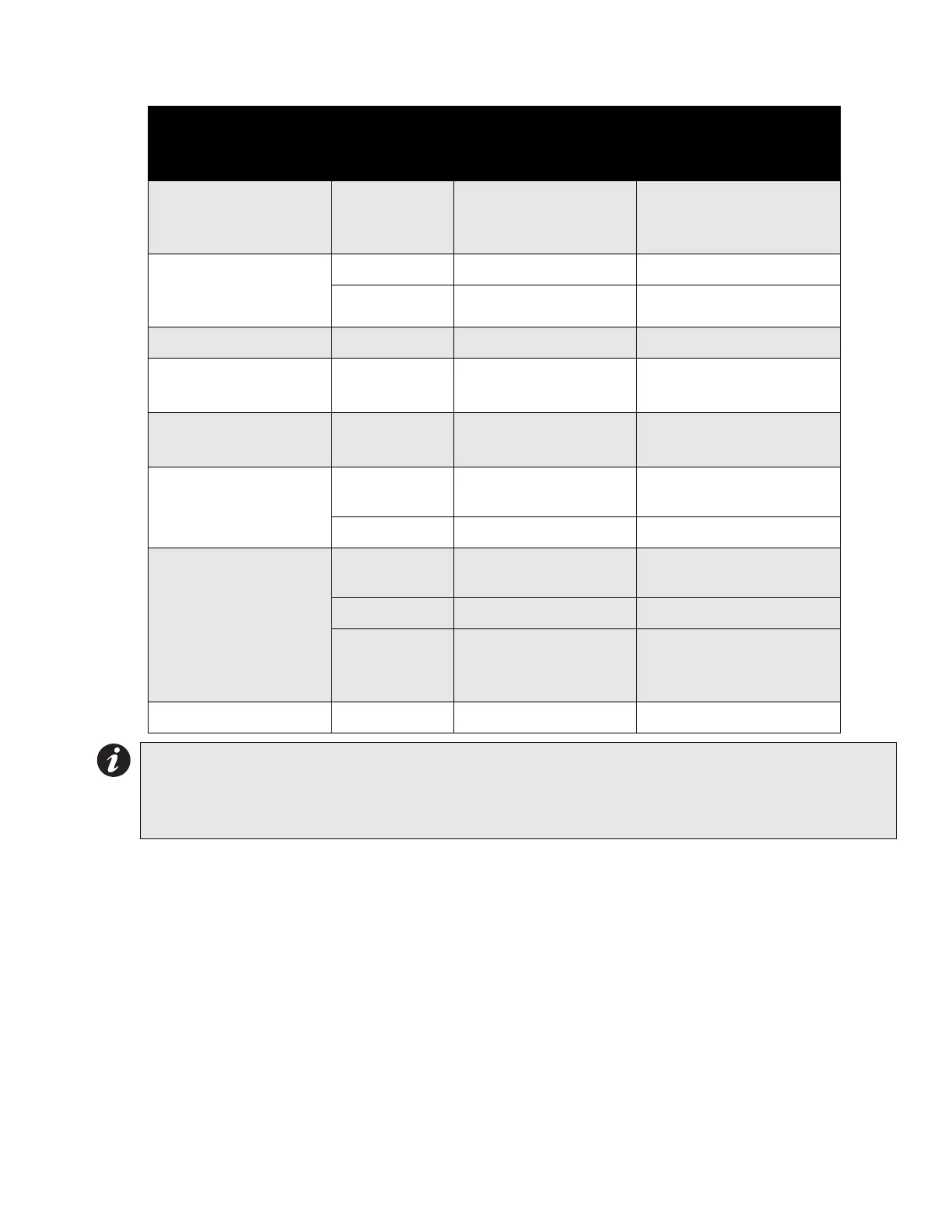
Table 4: Configuration DIP Switch Functions on DM-204 Module
When configuring the DM-204, keep in mind the following information:
• Only Indicating Circuit #4 may be configured for visual devices.
• If Initiating Circuit #7 is configured as waterflow, the corresponding verified selection becomes a retard
selection.
• If Initiating Circuit #8 is configured as alarm, the corresponding latching selection has no effect.
• If Initiating Circuit #8 is configured as supervisory, the corresponding verified selection has no effect.
• The selection of Class A/B (Style Z/Y) indicating circuits is only a matter of how they are wired. See connection
information on page 15.
• If Class A (Style D) initiating circuits are selected the appropriate board jumpers must also be set. Class B
initiating circuits 5 and 6 combine to create Class A Circuit #3, and Class B initiating circuits 7 and 8 combine to
create Class A Circuit #4. DIP switches for circuits 5 to 8 are ignored, and led indicators for circuits 5 to 8 are
non-functional.
Function
DIP Switch
on DM-204
Module
Switch “Off” Switch “On”
Indicating Circuit #3
Audible Device (Bell)
Only
Switch 6, #1 Silenceable Non-Silenceable
Indicating Circuit #4
Audible or Visual
Device
Switch 6, #2 Silenceable Non-Silenceable
Switch 6, #3 Audible Device (Bell) Visual Device (Strobe)
Not Used Switch 6, #4 ----------------- -----------------
Initiating Circuit #5
Alarm Only
Switch 5, #1 Normal Alarm Verified Alarm
Initiating Circuit #6
Alarm Only
Switch 5, #2 Normal Alarm Verified Alarm
Initiating Circuit #7
Alarm or Waterflow
Switch 5, #3 Normal
Verified Alarm / Retarded
Waterflow
Switch 5, #4 Alarm Waterflow
Initiating Circuit #8
Alarm or Supervisory
Switch 5, #5 Normal
Verified Alarm (no effect
on Supv.)
Switch 5, #6 Alarm Supervisory
Switch 5, #7
Non-Latching
Supervisory
(No effect on Alarm)
Latching Supervisory
(No effect on Alarm)
Not Used Switch 5, #8 ----------------- -----------------
Notes:
• After you change any configuration switches, perform a system reset.
• Do not use retard operation with any external retarding device; maximum retard may not exceed 120
seconds.