FA-200 Series Installation and Operation Manual
29
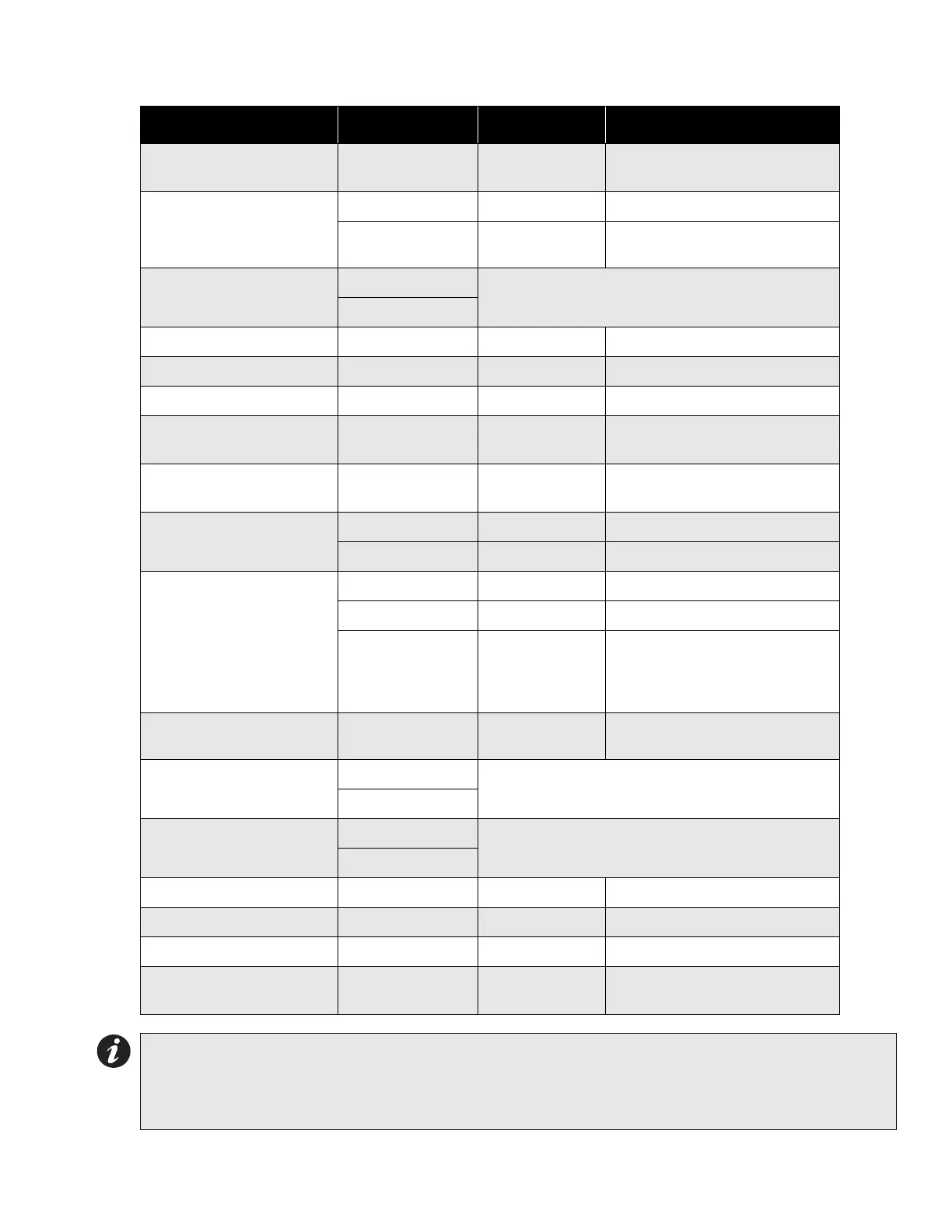
Table 3: Configuration DIP Switch Functions on Main Fire Alarm Board
Function DIP Switch Switch “Off” Switch “On”
Indicating Circuit #1
Audible Device (Bell) Only
Switch 13, #1 Silenceable Non-Silenceable
Indicating Circuit #2
Audible or Visual Device
Switch 13, #2 Silenceable Non-Silenceable
Switch 13, #3
Audible Device
(Bell)
Visual Device (Strobe)
# Remote Annunciators
Switch 13, #4
5 off, 4 off = None 5 off, 4 on = One
5 on, 4 off = Two 5 on, 4 on = Three
Switch 13, #5
Manual Signal Silence Switch 13, #6 Disabled Enabled
Fire Drill Switch 13, #7 Disabled Enabled
Aux. Disconnect Switch 13, #8 Disabled Enabled
Initiating Circuit #1
Alarm Only
Switch 11, #1 Normal Alarm Verified Alarm
Initiating Circuit #2
Alarm Only
Switch 11, #2 Normal Alarm Verified Alarm
Initiating Circuit #3
Alarm or Waterflow
Switch 11, #3 Normal Verified Alarm / Retarded Waterflow
Switch 11, #4 Alarm Waterflow
Initiating Circuit #4
Alarm or Supervisory
Switch 11, #5 Normal Verified Alarm (no effect on Supv.)
Switch 11, #6 Alarm Supervisory
Switch 11, #7
Non-Latching
Supervisory
(No effect on
Alarm)
Latching Supervisory
(No effect on Alarm)
Application of AC Power Fail
Delay
Switch 11, #8
No AC Power Fail
Delay
Apply AC Power Fail Delay
Signal Code
Switch 9, #1
2 off, 1 off = Temporal Code 2 off, 1 on = Continuous
2 on, 1 off = March Time 2 on, 1 on = California Code
Switch 9, #2
Auto Signal Silence
Switch 9, #3
4 off, 3 off = Disabled 4 off, 3 on = 5 Minutes
4 on, 3 off = 10 Minutes 4 on, 3 on = 20 Minutes
Switch 9, #4
Signal Silence Inhibit Switch 9, #5 None 1 Minute
Initiating Circuit Style / Class Switch 9, #6 Class B (Style B) Class A (Style D)
Aux. Devices Switch 9, #7 Non-Silenceable Silenceable
AC Power Fail Delay to
Aux. Devices
Switch 9, #8
24 Hour Standby
Standard
60 Hour Standby
Standard
Notes:
• After you change any configuration switches, perform a system reset.
• Do not use retard operation with any external retarding device; maximum retard may not exceed 120
seconds.