EasyManuals Logo

Mircom FX-2000 series User Manual

Mircom FX-2000 series
109 pages
To Next Page IconTo Next Page
To Previous Page IconTo Previous Page
Page #25 background imageLoading...
Page #25 background image
22
Mechanical and Chassis Installation
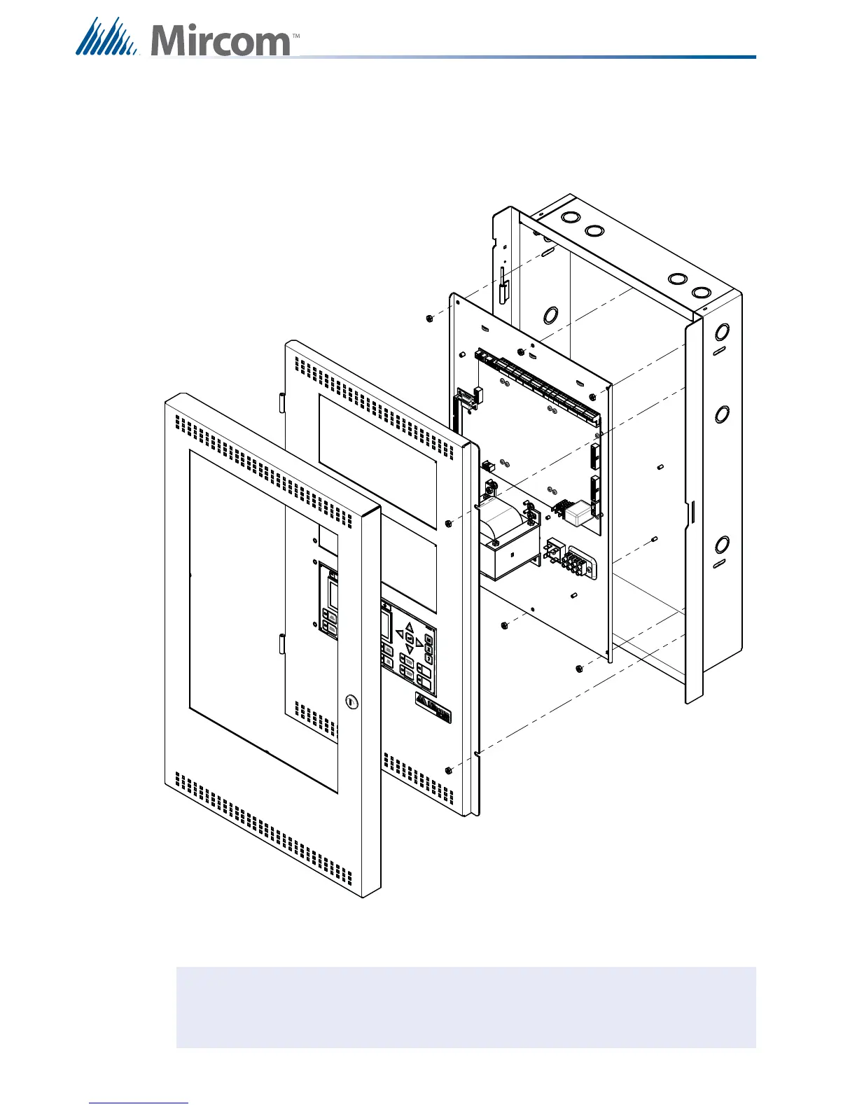
4.2.3 Mounting the Chassis into the UB-1024DS and DOX-1024DS/R Enclosure
The chassis is mounted using the six #8 hex nuts provided. Three across the top and three
across the bottom of the chassis. The inner door mounts over the chassis with two #8 hex
nuts.
Figure 10
Chassis Installation into Universal Enclosure UB-1024DS and DOX-1024DS/R
Note: Leave bottom of box conduit free for batteries.
i

Table of Contents

Other manuals for Mircom FX-2000 series

Questions and Answers:

Question and Answer IconNeed help?

Do you have a question about the Mircom FX-2000 series and is the answer not in the manual?

Mircom FX-2000 series Specifications

General IconGeneral
TypeFire Alarm Control Panel
DisplayLCD
NetworkOptional
CommunicationRS-232, RS-485
ProgrammingVia keypad or PC
SLC Loops1
NAC Outputs4
Communication (Additional)Optional Ethernet
Input Voltage120 VAC or 240 VAC, 50/60 Hz
Battery Charging Current1.5 A
Auxiliary Power Output24 VDC
Operating Temperature0°C to 49°C (32°F to 120°F)
Relative HumidityUp to 93% non-condensing

Related product manuals