EasyManuals Logo

Mircom FX-2000 series User Manual

Mircom FX-2000 series
109 pages
To Next Page IconTo Next Page
To Previous Page IconTo Previous Page
Page #69 background imageLoading...
Page #69 background image
66
Indicators and Controls
10.0 Indicators and Controls
Refer to Figure 45 and Figure 46 below for LED indicators, control buttons, and switch
locations associated with the main control displays.
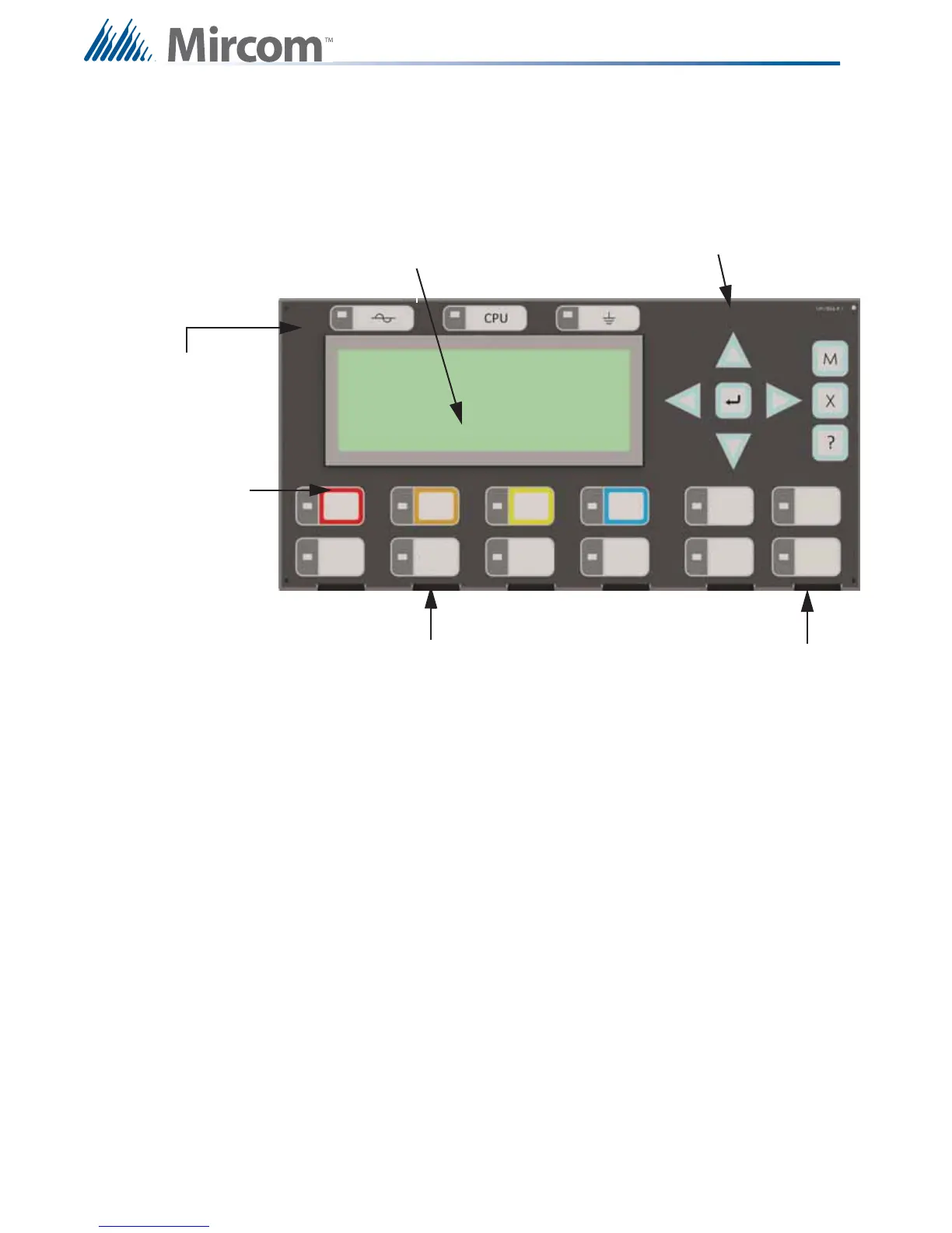
Figure 45 DSPL-420 Main Display Indicators and Controls
GENERAL
ALARM
BLDG
ACK
TBL
ACK
SUP
ACK
ALM
ACK
GENERAL
ALARM
CANCEL
FIRE
DRILL
SYSTEM
RESET
LAMP
TEST
SIGNAL
SILENCE
LCD Display - four lines,
20 characters per line
C u r s o r b u t t o n s a n d b u t t o n s f o r
M (MENU), X (CANCEL), ? (INFO)
and ENTER
ACK controls and
indicators for Alarm,
Supervisory, Trouble,
and BLDG (Monitor)
Indicators for AC On,
CPU Fault, and Ground
Fault
Controls & Indicators for Signal
Silence, Lamp Test, System
Reset, Fire Drill, General Alarm
(Two Stage only), General Alarm
Cancel (Two Stage only)
Two configurable
switches & amber LEDs

Table of Contents

Other manuals for Mircom FX-2000 series

Questions and Answers:

Question and Answer IconNeed help?

Do you have a question about the Mircom FX-2000 series and is the answer not in the manual?

Mircom FX-2000 series Specifications

General IconGeneral
TypeFire Alarm Control Panel
DisplayLCD
NetworkOptional
CommunicationRS-232, RS-485
ProgrammingVia keypad or PC
SLC Loops1
NAC Outputs4
Communication (Additional)Optional Ethernet
Input Voltage120 VAC or 240 VAC, 50/60 Hz
Battery Charging Current1.5 A
Auxiliary Power Output24 VDC
Operating Temperature0°C to 49°C (32°F to 120°F)
Relative HumidityUp to 93% non-condensing

Related product manuals