67
Indicators and Controls
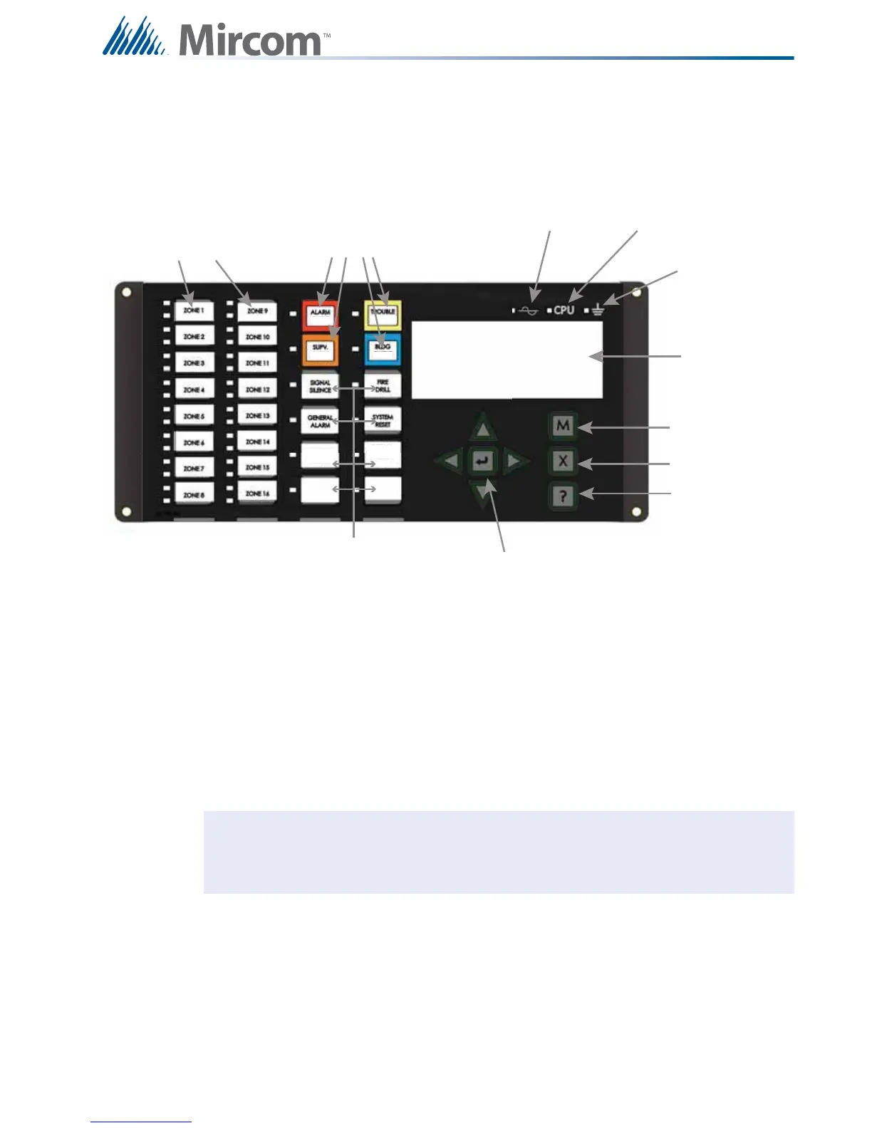
Refer to Figure 46 below for main display model DSPL-420-16TZDS. This display is similar to
the DSPL-420 shown in Figure 45 except for the extra 16 configurable bi-coloured LED zone
indicators and 16 trouble LED indicators.
Figure 46 DSPL-420-16TZDS Main Display Indicators and Controls
LED indicators are amber (trouble or supervisory), red (alarm), or green (AC On), and may
illuminate continuously (steady) or at one of two flash rates:
10.1 Paper Labels for Buttons and Indicators
Buttons and indicators are supplied with paper labels. These labels slide into the plastic label
templates on the face of the panel. Paper labels allow for easy English / French selection and
custom-printed zone information.
Fast Flash 120 flashes per minute, 50% duty cycle
Trouble Flash 20 flashes per minute, 50% duty cycle
Note: The General Alarm LED and pushbutton, and the General Alarm Cancel LED
and pushbutton, are active only on a system configured for “Two Stage.”
16 congurable
bi-coloured zone
indicators and 16
trouble indicators
Queue controls and
indicators for Alarm,
Supervisory,
Trouble and Monitor
AC On
Indicator
CPU Fault
Indicator
Ground Fault
Indicator
LCD Display
4 lines
20 characters
Menu
Cancel
Info
Cursor buttons
and Enter button
Control and Indicators for Signal
Silence, General Alarm, General Alarm
Cancel, Fire Drill, System Reset, Lamp
Test and Spare programmable Buttons
ACK
GENERAL
ALARM
CANCEL
ACK
ACK ACK
LAMP
TEST
 Loading...


