EasyManuals Logo

Mircom FX-2000 series User Manual

Mircom FX-2000 series
109 pages
To Next Page IconTo Next Page
To Previous Page IconTo Previous Page
Page #28 background imageLoading...
Page #28 background image
25
Display and Adder Modules Mounting Locations
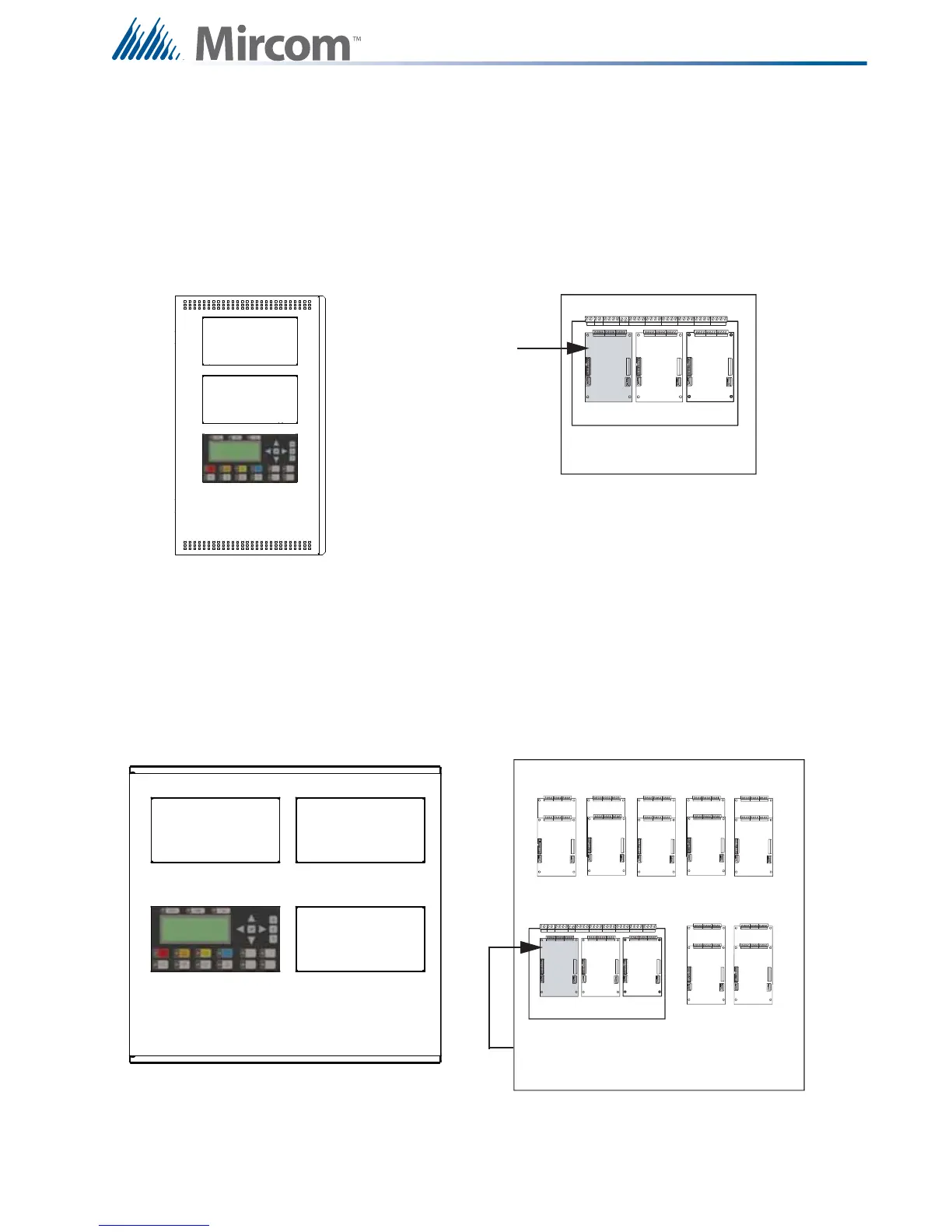
6.0 Display and Adder Modules Mounting Locations
6.1 FX-2003-6DS/FX-2003-12DS/FX-2003-6DS-16LED Compact
Main Chassis
Mounts in the UB-1024DS backbox and supports three circuit adder modules.
6.2 FX-2017(S)-12DS Mid-size Main Chassis
Mounts in the BBX-1072ADS or BBX-1072ARDS Enclosure, and supports three display
modules and 17 adder modules.
Exterior View Interior View
Slot is reserved for
PR-300 or UDACT-
300A. If not
required, this slot
can be used to
mount any of the
adder modules.
1
23
45
67
89101112
1314151617
FX-2000 Main Board
Slot is reserved for PR-300 or UDACT-
300A. If not required, this slot can be used
to mount any of the adder modules.

Table of Contents

Other manuals for Mircom FX-2000 series

Questions and Answers:

Question and Answer IconNeed help?

Do you have a question about the Mircom FX-2000 series and is the answer not in the manual?

Mircom FX-2000 series Specifications

General IconGeneral
TypeFire Alarm Control Panel
DisplayLCD
NetworkOptional
CommunicationRS-232, RS-485
ProgrammingVia keypad or PC
SLC Loops1
NAC Outputs4
Communication (Additional)Optional Ethernet
Input Voltage120 VAC or 240 VAC, 50/60 Hz
Battery Charging Current1.5 A
Auxiliary Power Output24 VDC
Operating Temperature0°C to 49°C (32°F to 120°F)
Relative HumidityUp to 93% non-condensing

Related product manuals