51
Field Wiring
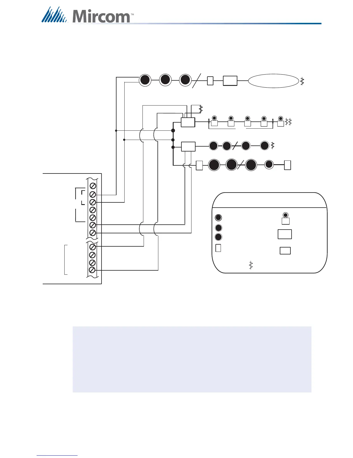
8.2 Analog Loop Wiring
8.2.1 Loop Terminal Connections - Class B
Figure 33 Loop Terminal Connections - Class B
Notes: Terminal blocks are “depluggable” for ease of wiring.
All power limited circuits must use type FPL, FPLR, or FPLP power limited cable.
Loop wiring: maximum loop resistance is 40 ohms total. These lines are fully
supervised.
Observe in and out polarity when using module and base isolators.
ANALOG
LOOP
CONNECTIONS
FX-2000
C
s
H
LEGEND
Addressable Smoke Det ector
wi t h St and ard Analog Base
Addressable Thermal Sensor
wi t h St and ard Analog Base
Convent ional Smoke Sensor
Addressable Manual
Pull Station
Combination
Horn/ Strobe
Addressable
Monitor Module
Addressable Supvr.
Out pu t Mod ul e
End -Of -Li ne- Resi st or
F
S
SO
2 Pair
4-WIRE
RESET TA B L E
SUPPLY
+
-
IND1 + (Y/Z)
IND1 + (Z)
IND1 - (Z)
IND1 - (Y/ Z)
F
S
LOOP 2
S
C
s
H
S
S
TWO WIRES
TWO WIRES
B
A
+
-
+
-
C
s
C
s
C
s
F
F
H
H
M
M
SO
M
COM ( - )
Conventional Heat Sensors
and Manual Pull Stations
MAIN FIRE ALARM BOARD
INDICATING
CI RCUI TS
NAC