32
Module Settings
7.3 RAX-1048TZDS Zone Display Module
Figure 18 Zone Display Module (RAX-1048TZDS)
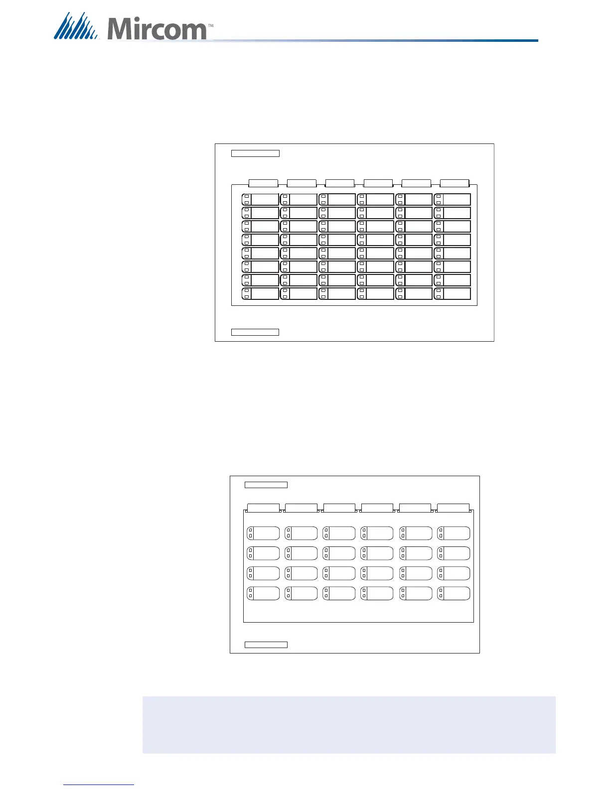
7.4 IPS-2424DS Programmable Input Switches Module
Figure 19 IPS-2424DS Programmable Input Switches Module.
P1 Cable connects to P2 of previous display module.
P2 Cable connects to P1 of next display module.
P1 Cable connects to P2 of previous display module.
P2 Cable connects to P1 of next display module.
Note: The zone display modules comes with laser printer-compatible slide-in paper
labels for zone labelling.
P
2
P
1
ZO
N
E
B
YP
A
SS
#1
ZO
N
E
B
YP
A
SS
#2
ZO
N
E
B
YP
A
SS
#4
ZO
N
E
B
YP
A
SS
#3
ZO
N
E
B
YP
A
SS
#5
ZO
N
E
B
YP
A
SS
#6
ZO
N
E
B
YP
A
SS
#8
ZO
N
E
B
YP
A
SS
#7
ZO
N
E
B
YP
A
SS
#9
ZO
N
E
B
YP
A
SS
#10
ZO
N
E
B
YP
A
SS
#12
ZO
N
E
B
YP
A
SS
#11
ZO
N
E
B
YP
A
SS
#17
ZO
N
E
B
YP
A
SS
#18
ZO
N
E
B
YP
A
SS
#20
ZO
N
E
B
YP
A
SS
#19
ZO
N
E
B
YP
A
SS
#13
ZO
N
E
B
YP
A
SS
#14
ZO
N
E
B
YP
A
SS
#16
ZO
N
E
B
YP
A
SS
#15
ZO
N
E
B
YP
A
SS
#21
ZO
N
E
B
YP
A
SS
#22
ZO
N
E
B
YP
A
SS
#24
ZO
N
E
B
YP
A
SS
#23