EasyManuals Logo

Mircom FX-2000 series User Manual

Mircom FX-2000 series
109 pages
To Next Page IconTo Next Page
To Previous Page IconTo Previous Page
Page #34 background imageLoading...
Page #34 background image
31
Module Settings
7.2.1 DSPL-420 Main Display Module
Figure 16 DSPL-420 Main Display Module
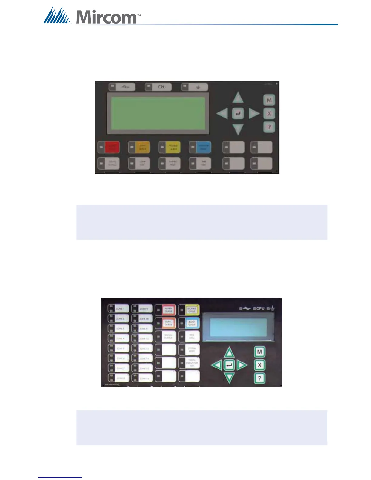
7.2.2 Optional DSPL-420-16TZDS Display Module
Figure 17 DSPL-420-16TZDS Main Display Module with 16 Zone LEDs
P1 Cable connects to P14 of main fire alarm module
P2 Connection to P1 of any adder display module if used.
Note: The main display module comes with slide-in paper labels including both English
and French slide-ins, and laser printer-compatible blanks for zone labelling.
P1 Cable connects to P14 of main fire alarm module
P2 Connection to P1 of any adder display module if used.
Note: The main display module comes with slide-in paper labels including both English
and French slide-ins, and laser printer-compatible blanks for zone labelling.
i
i

Table of Contents

Other manuals for Mircom FX-2000 series

Questions and Answers:

Question and Answer IconNeed help?

Do you have a question about the Mircom FX-2000 series and is the answer not in the manual?

Mircom FX-2000 series Specifications

General IconGeneral
TypeFire Alarm Control Panel
DisplayLCD
NetworkOptional
CommunicationRS-232, RS-485
ProgrammingVia keypad or PC
SLC Loops1
NAC Outputs4
Communication (Additional)Optional Ethernet
Input Voltage120 VAC or 240 VAC, 50/60 Hz
Battery Charging Current1.5 A
Auxiliary Power Output24 VDC
Operating Temperature0°C to 49°C (32°F to 120°F)
Relative HumidityUp to 93% non-condensing

Related product manuals