27
Display and Adder Modules Mounting Locations
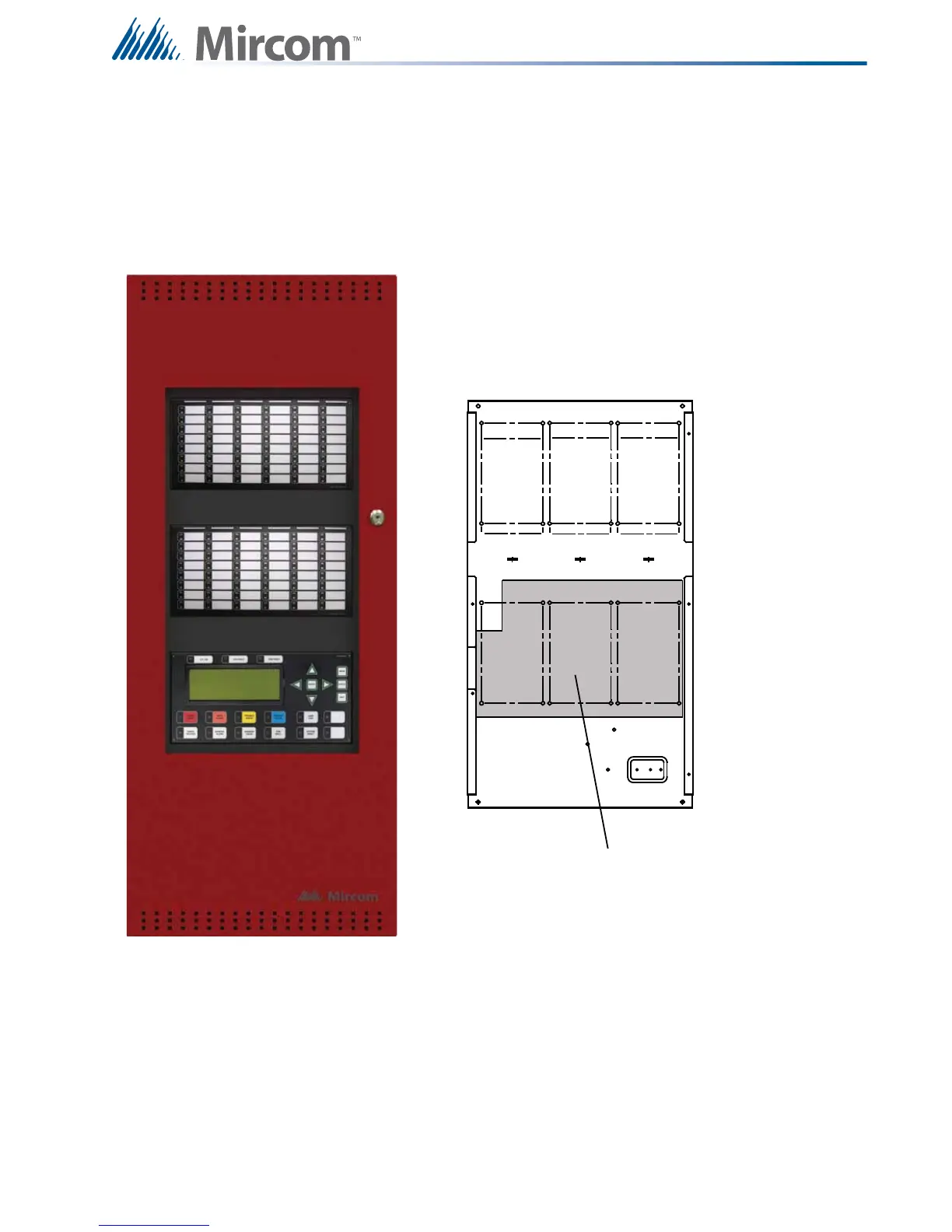
6.5 Mounting the Boards to the BBX-1024XT Chassis
The main board is mounted to the chassis and is shipped out this way. Mounts up to 9 adder modules
and one display module such as RAX-1048TZDS Programmable 48 Zone and Trouble LED display
module, IPS-2424DS Programmable Input Switches module and FDX-008W Fan Damper module.
Figure 13 FX-2003-12XT in a BBX-1024XT Enclosure
Inside Chassis for mounting adder
modules. Three modules can be
mounted over the main re alarm
board and six above the main re
alarm board stacked three over
three.
Three adder modules
mounted over main re
alarm board.
Main Fire Alarm Board
3
4
5
6
7
8
9
2
1