48
Module Settings
.
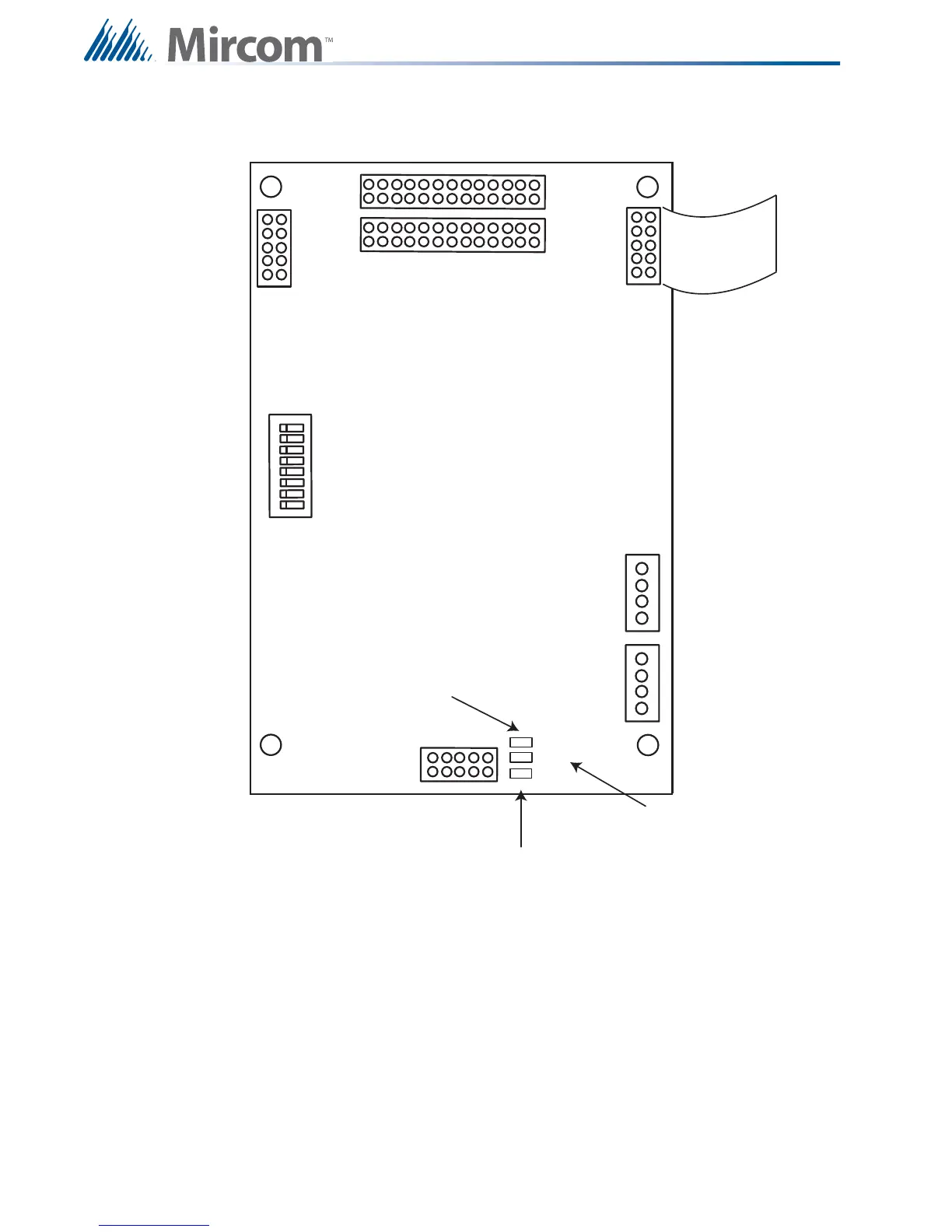
Figure 30 ALC-H16 Hardwire Loop Controller Module
Mount the ALC-H16 Hardwire Loop Controller module as shown on Module Mounting
Locations View #2 on page 24 and ECX-0012 Expander Chassis for FX-2009-12DS on
page 26. The module may be mounted over the main chassis board or in any position that an
adder module is mounted.
There is no wiring at the ALC-H16 Hardwire Loop Controller module, but there is wiring at the
16 standard conventional adder modules. For conventional hardwire circuit wiring refer to
Hardwire Detection Module (DM-1008A) Terminal Connections on page 57, Hardwire Signal
Module Terminal Connections on page 58, and Hardwire Relay Module Terminal
Connections on page 59 for the specific module you are wiring.
RS-485
CABLE
RS- 4 8 5
DDRESS
DIP
SW I TCH
BDM PORT
POWER
CABLE
(OUT)
POWER
CABLE
(IN)
P4
P12
P13
P3
P2
P1
ON
1
8
JW3
JW1
JW2
JW2 - THE
JUM PER IS
KEPT HERE
FOR
NORMAL
OPERATION
JW1 - PINS ARE
SH O RTED
MOMENTARILY TO
RESET
H A RD WA RE
JW3 - JUM PER
FROM JW2 IS
PLACED HERE TO
BYPASS
WATCHD OG FOR
FA C T O RY
DOWNLOADING
USING BDM
D I P SWI TCH ES A RE FOR
THIS BOARD=S ADDRESS.
SW- 1 I S TH E LEA ST
SIGNIFICANT DIGIT (BINARY).
ACTIVE POSITION IS OFF.
P12 IS USED TO CONNECT SECOND GROUP OF 8 ADDER MODULES
P13 IS USED TO CONNECT FIRST GROUP OF 8 ADDER MODULES