EasyManuals Logo

Mircom FX-2000 series User Manual

Mircom FX-2000 series
109 pages
To Next Page IconTo Next Page
To Previous Page IconTo Previous Page
Page #67 background imageLoading...
Page #67 background image
64
Field Wiring
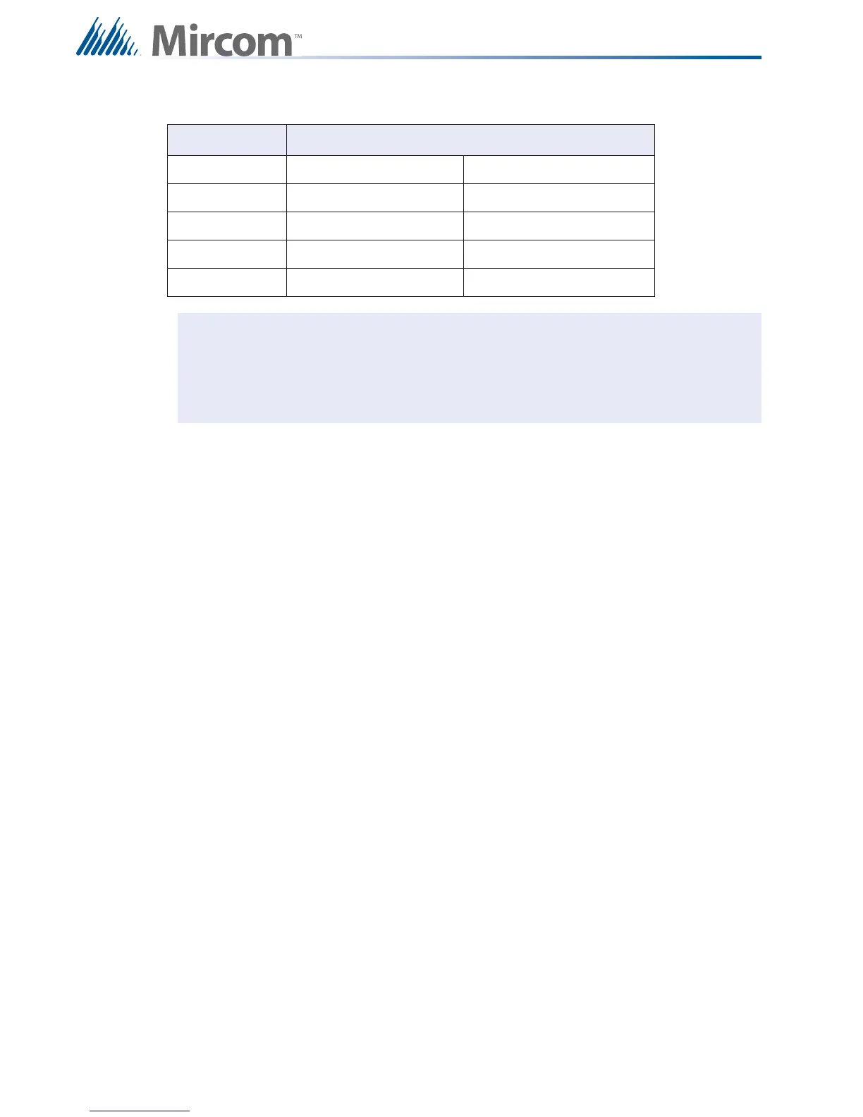
Table 16 Analog Loop Wiring
Wire Gauge Maximum Wiring Run to Last Device (ELR)
(AWG) ft m
18 3132 955
16 4980 1518
14 7971 2429
12 10,000 3049
Notes: Line capacitance shall not exceed 0.5 mF
Inductance shall not exceed 1 mH.
Resistance shall not exceed 40 ohms.
Power Wiring Use Table 15 NAC Circuit Wiring Table on the previous page to see
the wiring information for the remote annunciator being used.
RS-485 Wiring See the wiring information for the remote annunciator being used.
4-Wire Smoke
Wiring
The maximum allowable current is 0.2 amperes. The maximum
allowed voltage drop is 1 volt. Refer to Table 15 NAC Circuit Wiring
Table on the previous page.
Shield for Analog
Loop Wiring
Only twisted pair is recommended, but if shielded twisted pair is used,
wire shield at the start and the end of the loop to the terminals marked
Shield at the loop adder board.
i

Table of Contents

Other manuals for Mircom FX-2000 series

Questions and Answers:

Question and Answer IconNeed help?

Do you have a question about the Mircom FX-2000 series and is the answer not in the manual?

Mircom FX-2000 series Specifications

General IconGeneral
TypeFire Alarm Control Panel
DisplayLCD
NetworkOptional
CommunicationRS-232, RS-485
ProgrammingVia keypad or PC
SLC Loops1
NAC Outputs4
Communication (Additional)Optional Ethernet
Input Voltage120 VAC or 240 VAC, 50/60 Hz
Battery Charging Current1.5 A
Auxiliary Power Output24 VDC
Operating Temperature0°C to 49°C (32°F to 120°F)
Relative HumidityUp to 93% non-condensing

Related product manuals