EasyManuals Logo

Mircom FX-2000 series User Manual

Mircom FX-2000 series
109 pages
To Next Page IconTo Next Page
To Previous Page IconTo Previous Page
Page #9 background imageLoading...
Page #9 background image
6
System Components
3.2 Auxiliary Modules
The following table describes the auxiliary modules used with the FX-2000.
ALC-396S
Dual Intelligent Analog Loop Controller
Module
DM-1008A, SGM-1004A,
RM-1008A
Conventional Circuit Adder Modules,
Detection, Signal and Relay.
DSPL-420-16TZDS
Optional main display with 16
configurable bi-coloured LEDs.
This display is included in the
FX-2003-6DS-16LED chassis package.
Table 3 FX-2000 Auxiliary Modules
Model Description
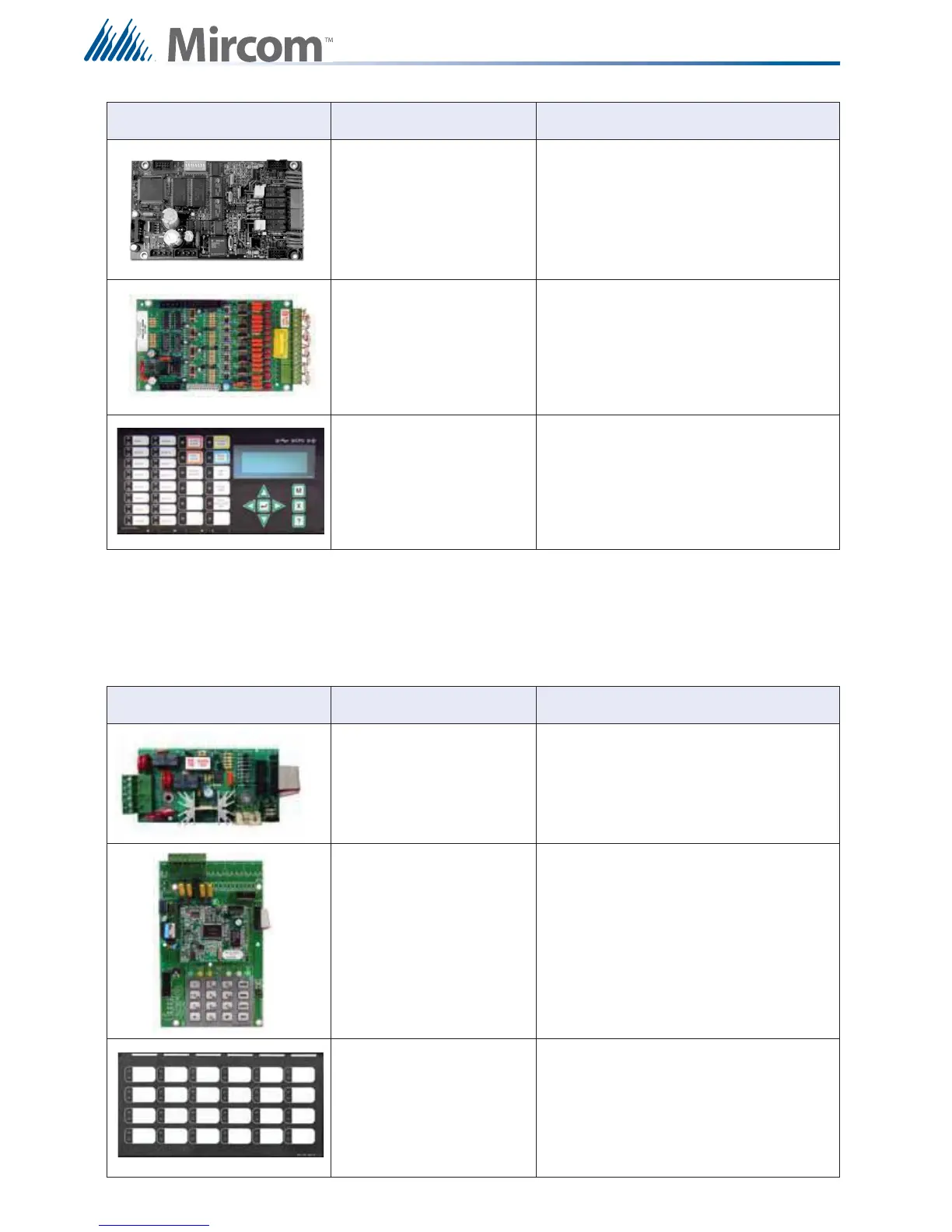
PR-300 Polarity Reversal and City Tie Module
UDACT-300A Digital Communicator/Dialer Module
IPS-2424DS Programmable Input Switches Module
Table 2 FX-2000 Adder Modules
Models Description

Table of Contents

Other manuals for Mircom FX-2000 series

Questions and Answers:

Question and Answer IconNeed help?

Do you have a question about the Mircom FX-2000 series and is the answer not in the manual?

Mircom FX-2000 series Specifications

General IconGeneral
TypeFire Alarm Control Panel
DisplayLCD
NetworkOptional
CommunicationRS-232, RS-485
ProgrammingVia keypad or PC
SLC Loops1
NAC Outputs4
Communication (Additional)Optional Ethernet
Input Voltage120 VAC or 240 VAC, 50/60 Hz
Battery Charging Current1.5 A
Auxiliary Power Output24 VDC
Operating Temperature0°C to 49°C (32°F to 120°F)
Relative HumidityUp to 93% non-condensing

Related product manuals