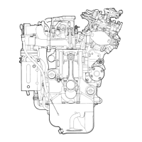
Differential
bypass
valve
(Yflth
switch)
r--~:r-...,
TO
MAIN
OIL GALLERY
FROM
OIL
PUMP
__
=~~J
-"""'
~
Relief
valve
J
TO OIL PAN
Fig. 3-13 Oil flow diagram
order
to
prevent any serious
trouble, seizure for
ex-
ample,
that
might be caused
by lack
of
oil. Whenever the
valve set
to
perform so, of
which the operator
will
be
signalled by alarm lamp
in
front
of
his seat, element
must
be replaced
at
the
earliest possible opportunity, for lubrication with unfiltered oil
will
affect moving parts.
The above alarm tamp
is
set alight,
as
soon
as
the valve opens
to
perform such
an
emergency bypassing, by contactor
that
is
attached
to
it
for
that
purpose.
3-4
Oil
pressure
Under ordinary weather conditions and
at
usual engine speed, oil pressure
is
kept
between 3 and 4kg/cm
2
by relief valve on oil filter cover. (The lowest permissible
pressure
is
2kg/cm
2
).
Model
40Q50
engine
is
provided, at option, with either an
oil
pressure gauge or an oil pressure alarm switch (which puts alarm lamp alight at a drop
below O.5kg/cm
2
).
1)
Under the following conditions,
oil
pressur~
often goes
out
of the
given
range,
but
will
usually become normal
as
the engine
is
run.
a)
When the engine has
not
yet
warmed up, i.e., soon after its starting.
In
this
case,
oil
pressure goes, above the standard range, claiming for its good
warm-up through low-speed idling.
b)
When, after a warm-up,
the
engine
is
let
to
idle, oil pressure drops low. But
this means nothing wrong so far
as
it remains above O.5kg/cm
2
•
2)
Any other drop of oil pressure than incidental
to
the above case
will
lead some
serious trouble; hence the necessity
to
check
as
follows and take necessary
measures.
a)
Is
oil
level
high enough? It must be above lower mark
line'
on oil
level
gauge.
b)
Anything
is
wrong with oil presSure gauge and its piping?
Check also alarm switch and
lamp, measuring
oil
pressure with an oil pressure
gauge.
c)
Any leak
in
oil line? Other probable causes are:
d)
Oil
pump suction-side piping
is
inhaling air.
e)
Bearings worn down.
-
21-
 Loading...