Injection pump full load stopper
Seal 1
Torque spring
Seal 2
Fig.
3-31
RUV Governor
---------------
*GOVERNOR (Model RSV,bosch
type)
(1)
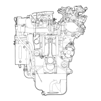
STRUCTURE AND OPERATION
Fig. 1
is
the
open·up view of the sectioned governor and its parts and Fig. 2 shows
the
disposition
of
such patts .
.
In
the
RSV type Mechanical AII·speed Governor, the flyweight·holder and flyweight
of
the
revolving part
of
the
governor are attached
to
the
comshaft of
the
injection pump.
The
two
flyweights revolve around
the
flyweight pin which
is
inserted
in
the
flyweight
holder, and when
the
flyweights opens themselves outside,
the
shoulder of
the
guide·bush
is
pushed by
the
roller toward
the
oxis.
The
guide-bush
slidi"ng
on the cylinderical surface of flyweight·holder may move freely
with
the
flyweight·holder, and the guide-bush
is
contacted
to
the
shifter by means
of
bearing.
The
shifter may be moved only longitudinally toward the axis. The trunnion
of
the
shifter
is
inserted
in
the
guide-lever which hung by the pin
of
the
governor-cover like a bob
and prevents
the
rotation of
the
shifter. A pin
is
attached
to
the
position slightly above
the
coupling
point
of
guide-lever and shifter
with
wax.
The
floating-lever
is
attached
to
either
left point or right
point
of the pin so
that
the
floating-lever may revolve (the left
or
right
point
of
the pin may be fixed
the
side
of
the
governor
to
which
the
governor pump
is
attached). The pin attached
to
the lower end
of
the
floating-lever with wax
is
inserted in
the
fork.
The
floating-lever contacts with
the
control-rack of
the
injection pump on
the
upper
end
of
the
revolving axis through the link which involves
the
leaf-spring, the link-pin and
the
split-pin. The start-spring
is
attached
to
the
other
end of
the
floating lever. This spring
is
operated
at
the
r.p.m. lower than
that
of
the
idling. One of
the
ends of this spring
is
-
34-
 Loading...