In
the
case
that the injection starting
angle needs
to
be newly set for such
reasons
as
replacement of the injection
pump with a
new
unit, do
as
follows.
1)
First locate the top dead center
of
#1
cylinder compression stroke,
turning crank shaft. For this, turn
crank jaw with a wrench
if
it
permits easy access of hand, or
ring gear by a tooth after another
with a screw driver, if it does not.
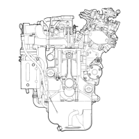
Fig. 3-23
TIming mark on
injection pump
Go on turning it until symbol
T on crank shaft pulley or symbol 1.4 on
flywheel exactly meets the pointer, and
#1
cylinder piston
will
be
at
top
dead
center. But assuring this, open rocker case cover and make sure
that
both
#1
cylinder inlet and exhaust valves keep proper clearance.
2)
With
#1 cylinder piston thus placed
at
top dead
cente~,
read
at
what crank
angle injection
will
start. For this, take the following steps.
3) Loosen off
#1
cylinder injection pipe so that a little fuel remains
in
the upper
part of delivery
valve
holder. Slowly turn crank shaft
in
its
usual
direction (that
is,
clockwise
as
viewed from fan), and fuel
level will
start swelling. Read crank
angle at
that
moment.
4) In
case
injection timing needs
to
be
set ahead, move injection pump body little
by
little
in
the reverse direction
that
its camshaft
revolves
(or toward
crankcase). Note
that
graduations on pump flange corresponds each
to
SO
of
crank angle.
4-6 Governor (pneumatic)
DIARHRAGM
AIR PIPE
FULL
LOAD STOPPER
NEGATIVE PRESSURE
CHAMBER
¢=
,.....,.,.......~
__
AIR
INLET
INLET
VALVE
Fig.
3-24 Scheme of pneumatic governor
-
28-
 Loading...