In
appearance
the
flange looks identical
to
that
of
our
conventional
type
hand
timer,
but
has inside
two
legs
that
project
in
the
same phase with flange teeth
and
keep
contact
with
the
curves surfaces
of
the
flyweights.
In
these
legs
are machined
the
other
seats
for
timer springs. Each timer spring
is
held in
the
said pair
of
seats,
that
is, in the
bearing pin by
one
end and
in
the
leg
by
the
other.
These major components are housed
in
timer
case, which
is
screwed
to
the
flyweight holder.
Fig.
3·33
A shows
the
time
at
a standstill. Being free from centrifugal force, the
flyweights
do
not
lift
at
all and
timer
springs are
now
longest
in
their setting length.
Fig.
3·33
B illustrates how
the
timer works
at
the
max. engine speed. Centrifugal
force
is
now
making
the
flyweights lift.
In
the
picture
the
letter B indicates flange
leg, whose phase with
the
pump driving
shaft
of
the
engine
is
designed
to
remain
constant.
So
the
lift pulls bearing pin A over
the
distance
E,
which results in turning
the
pump
camshaft
on
the
driving
shaft
so
as
to
put
ahead
the
injection timing.
(A)
ATA
STANDSTILL
(B)
AT
MAX. SPEED
Fig. 3-33
Timer
flyweight
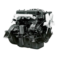
The
timer
for
Model 4DQ50 Engine
is
intended for clockwise revolution and
provides a max. angle
of
lead
of
eO
as measured on
the
pump camshaft.
At
a standstill,
it
keeps
the
injection slowest.
The
automatic
timer
was assembled with 150gr.
of
grease inside and unless leaked
by
chance, needs
not
be refilled. When
the
timer disassembled, change grease
for
new
one.
4-9 Measurement
of
engine speed
1) A
drop
of
engine speed below
the
specified level will disturb
the
engine
working
up
to
the
given efficiency, while a rise above it will cause
the
overrunning
of
the
engine itself
or
of
the
vehicle
it
drives. Therefore,
both
max.
and
rated speeds
must
be always as specified.
2)
As mentioned befQre,
pneumatic
governor governs engine speed in one-to·one
proportion
to
the
percentage
of
Venturi opening, hence permits the engine
to
-
46-
 Loading...