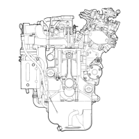
The view
of
timing gear train with cover off
is
shown
as
(Fig. 5-10). To install gears
that
were taken apart, bring #1 cylinder piston
to
top
dead center and holding it there,
mesh gears one after another with idler,
following their numerical meshing marks,
as
illustrated
in
Fig. 5·10.
Align autotimer key way with mark line
on
injection pump gear.
6·2 Valve timing
To install gears according
as
indicated with numerical meshing marks dispenses with
the trouble
of
checking
valve
timing. For reference sake, however,
valve
timing diagram
is
given
in
Fig. 5-11.
Every
cam having a symmetrical profile, checkup of
valve
tim
ing
requires
to
measure crank angle,
at
max. cam lift
to
see
if it equal
to
the angle indicated
with broken line
in
Fig.
5·11. The procedure
is
detailed
as
follows.
Take for instance, No.1 cylinder inlet and exhaust
valves.
First set
valve
clearances
by means of plane plates with uniform thickness. of
3-4mm,
and put the thinnest
INLET
VALVE
EXHAUST
CLOSES.
~,
.......
VALVE
OPENS.
Exhaust
c~m-~-~
. j
....
'·Inlet
cam
max.
tift
max.
lift
'>11".
A
1'·
.
-:
4"~~O
..
..
:5
j,
::>,...
..
~
.!
.....
J • C
~
Q.~
...
- Crank Angle
Fig.
5-11
Valve timing
-
75-
~!
,c
:;
e
..
II
Q.
~~!
...
~
~.2
 Loading...