α
Simple Application Controller
How to Use
α
αα
α
Series Controllers - Getting Started 6
27
ENG
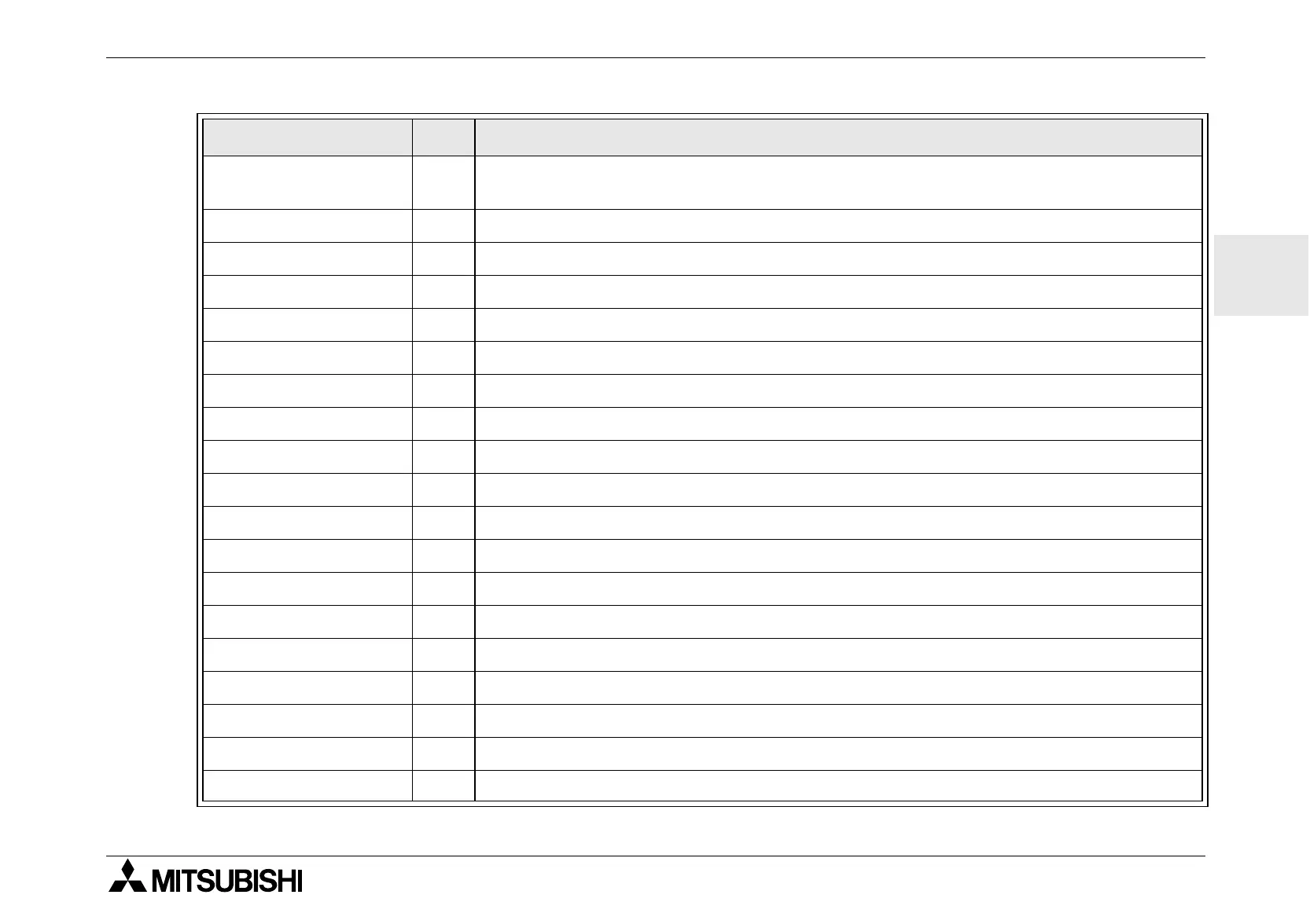
*Number of bytes varies with input data.
NOR 19
Not OR; Output Off when at least one Input is On, Unused inputs considered
Off
NOT 10 Inverts a signal; changes an Off to an On and vice versa
BOOLEAN * Logic equation using AND, OR, XOR, and NOT
SET/RESET 14 Latch a relay in SET or RESET position, give Set or Reset priority
DELAY 19 Delay a signal on the Rising, Falling, or both Edges
ONE SHOT 17 Send a single pulse; Time or Input signal based, Reset pin available
PULSE 10 Send a Pulse on the Rising, Falling, or both Edges
FLICKER 19 Send a pulse train; On/Off times, repetitions, duration, or continuous operation
ALT 13 Output alternates turning On or Off with each input pulse
COUNTER 16 Count upwards on pulses, can reset at an input value or signal
U/D COUNTER 22 Up and Down Counter with Preset Input and Clear functions
COMPARE 17 Compare two values for <,>,=,<=,>=,<> (Analog, Direct Set, or FB values)
TIME SWITCH * Use the RTC to turn output On/Off; Calendar or weekly schedule
OFFSET GAIN 22 Manipulate Analog Values; y = A/B*x + C; Set High and Low Limit Values
DISPLAY * Display Messages or Data on the LCD display
ZONE COMPARE 20 Compare a value to a range of values (Analog, Direct Set, or FB values)
SCHMITT TRIGGER 19 Turn an Input On at the High Value and Off at the Low Value (or vice versa)
HOUR METER 19 Records the accumulated time an Output or Input signal has been ON
System Outputs 10 Controls External Devices through Relays and Transistors.
Table 6.2: Function Block Description
Function Block Byte Description
 Loading...


