7
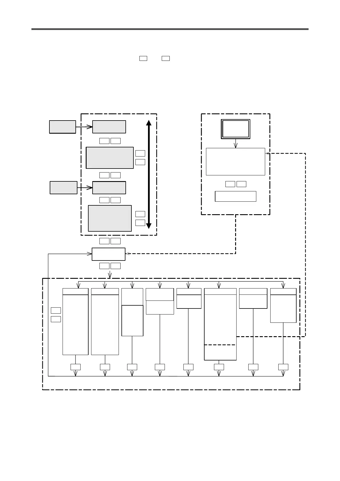
3.2 Overall flow of screen
T h e f i g u r e b e l o w s h o w s t h e o v e r a l l c o n f i g u r a t i o n o f s c r e e n d i s p l a y s .
The data can be read in turn using the and keys.
Four major screens are available. Those are the initial setting screen, operator screen of usual operation,
engineer screen for system setting and memory cassette data transfer screen. This section shows the over-
all flow of the operator screen that is used in usual operation and the engineer screen. For other screens,
refer to the relevant sections.
*1 It is displayed exclusively when the LE-40MD is connected.
*2 It is displayed and can be set when the LE-40MD is not connected or when the LE-40MD is connected
but not turn on.
However, the set value is invalid. (The set value is valid when the LE-40MD is connected.)
T S
Power on
for the
first time
AUTO
switch
Tension set
screen
Stall setting
Initial Dia. setting (*1)
(New reel setting)
(Taper setting)
Manual set
screen
Tension monitor 1
Tension monitor 2
(Diameter monito)
Length monitor (*1)
Speed monitor (*1)
Password
screen
MANUAL
switch
Initial setting
Pass word
Full scale setting
Zero/Span adjustment
Confirm setting
Initial setting
screens
Operator screens
(usual operation)
SWITCH
Unit
Control
reels
Number of
reels
Taper
Actuator
Stall
AI2
AI3
MC5
MC6
TENSION
Filter
(Display)
Filter
(Output)
ZT
Zero
adjustment
Span
adjustment
Full scale
START
AND
STOP
Start‚s
Stop‚s
Stop‚f
Stop‚a
Out‚f
REEL
CHANGE
Preset T
Cut torque
REEL
Mech.loss
Diameter
OTHERS GAIN
Gain
adjustment
Instal mode only
Including all functions except the password setting on the initial setting screen .
Settings made during the initial setting can be changed as necessary .
Engineer screens (system parameters and operation parameters)
Contact
monitor
Voltage
monitor
MD monitor *1
Revolution *1
signal
Set
inhibition
Initialize
memory
T S
T S
T S
T S
T S
T S
T
T
S
T
S
T
S
T T T T T T
40 MD *2
Diameter
calculation
unit set
T