3. Setup
3 - 87
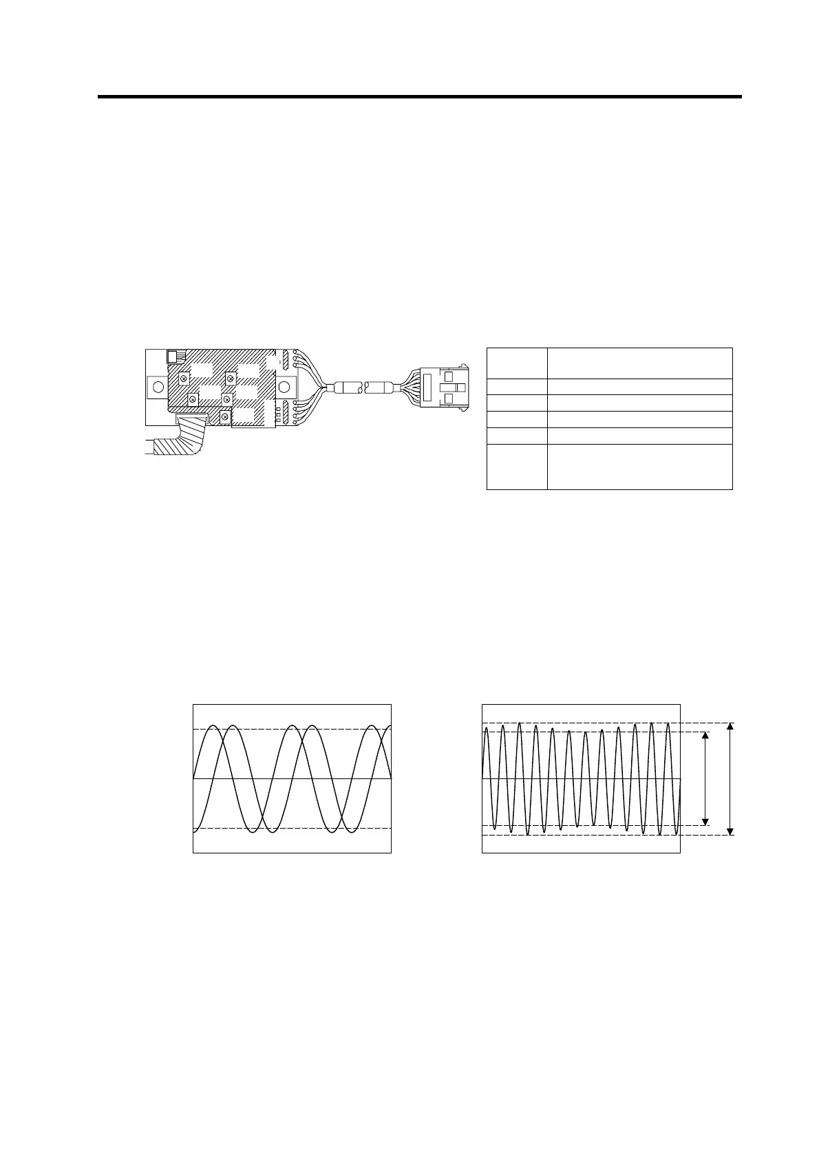
(4) Adjusting the A phase and B phase output signal
1) Set the drive unit in the open loop operation state. (Set the spindle parameter SP038. bit F to
"1" and turn the NC power ON again.) There are cases when sudden speed changes cannot
be followed during open loop operation, so gradually change the speed command.
2) Forward run the motor and rotate the PLG at the reference speed.
3) Using the PCB volume VR1 to VR4, adjust so that the A phase and B phase signals are within
the specified range. If the correct waveform cannot be attained even after adjusting with VR1
to VR4, adjust the gap again.
4) Reverse run the motor and rotate the PLG at the reference speed.
5) Adjust the output waveform by adjusting VR1 to VR4 in the same manner.
VR1
VR2
VR4
VR3
VR5
G
B
A
Z
PCB section
6) Set the drive unit to the closed loop operation state (normal operation).
7) Run the motor at the maximum speed, and confirm that the A phase and B phase output
voltage peak value is larger than 0.8V on both the plus side and minus side during both
forward run and reverse run.
8) Run the motor at the reference speed, and confirm that the A phase and B phase output signal
envelope is 0.4V or less.
The envelope is calculated by the expression below.
(Envelope) = (Maximum amplitude α) - (Minimum amplitude β)
9) If the envelope is larger than the designated value, the deflection of the detection gears' outer
diameter may be large, so check the deflection.
Example of A phase/B phase signal waveform
during forward run at maximum speed
Definition of envelope
Volume function
Check
terminal
Signal name
VR1 A phase offset adjustment
VR2 A phase gain adjustment
VR3 B phase offset adjustment
VR4 B phase gain adjustment
VR5
Z phase pulse width adjustment
(Already adjusted before
shipment)
A phase
B
hase
0.8
Voltage [V]
-0.8
0
Time
Voltage [V]
0
Time
Minimum am
litude:
Maximum am
litude: α

 Loading...


