Appendix 3. EMC Installation Guidelines
A3 - 7
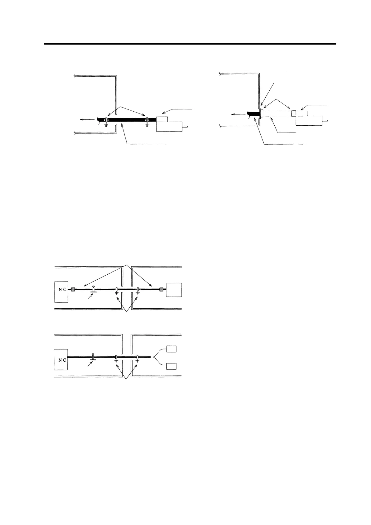
Appendix 3-5-5 Spindle motor power cable
Control panel
To drive unit
Earth with
P or U clip
Terminal
box
Shield cable
Spindle moto
Control panel
To drive unit
Conduit
connecto
Conduit
Cabtyre cable
Terminal
box
Earth with paint mask
Using shield cable Using conduit
(1) Use four wires (3-phase + earthing) for the power cable that are completely shielded and free from
breaks.
(2) Earth the shield in the same manner as the servomotor power cable.
(3) When not using a shield cable for the power cable, use a conventional cabtyre cable. Use a metal
conduit outside the cable.
(4) Earth the power cable on the control panel side at the contact surface of the conduit connector and
control panel side wall in the same manner as the servomotor power cable. (Mask the side wall of
the control panel with paint.)
(5) Earth at the conduit connector section in the same manner as the servomotor power cable.
Appendix 3-5-6 Cable between control panel and operation board panel
Control
anel
Operation board panel
Clamp fitting
enclosed with NC
Board
SH11 cable (signal cable)
Ferrite core (Within 10cm from device)
Earth with P or U clip
Control
anel
Operation board panel
Clamp fitting
enclosed with NC
Board
PD05 cable (power supply cable)
Earth with P or U clip
(1) Use a shield cable for the cable between the
control panel and operation board.
(2) Earth the shield in the same manner as the
other cables.
(3) Insert a ferrite core in the SH11 cable at a
position within 10cm from the device.
(This provides a better effect.)
The PD05 cable is used with the MELDAS500
Series.
Refer to the EMC INSTALLATION GUIDELINES
for each NC for details.

 Loading...


