2. Wiring and Connection
2 - 30
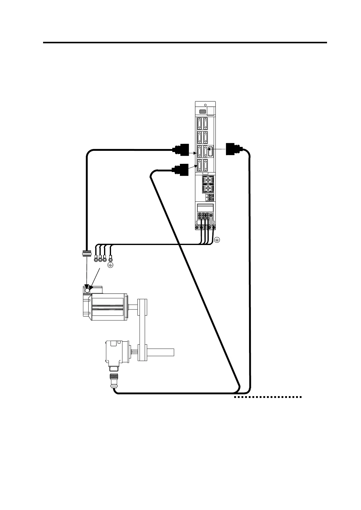
(4) Connecting the encoder for C axis control
Refer to section (1) for connection with the spindle motor.
MDS-C1-SP
Option cable : CNP7A
Connect to ENC
connector on NC side
CN6
UV W
Max. 30m
CN5
Spindle motor
Power cable
Option cable : CNP5S
U V W
Option cable : CNP67A
C axis control
Encoder
Spindle
CN7
Option cable : CNP71A
Supplement
1. The C axis control function is connected to the CN7 connector.
2. When using both the C axis control function and orientation function, two cables (two-wire cable) are
connected from the detector.
3. The orientation signal connected to CN5 or CN6 can be connected to the NC with the differential
output from the CN8 connector.

 Loading...


