2. SIGNALS AND WIRING
2 - 11
2.3 Signal (device) explanations
The connector pin No. column in the table lists the pin Nos. which devices are assigned to by default.
For the I/O interfaces (symbols in I/O division column in the table), refer to section 3.9.2 of "MR-JE-_A Servo
Amplifier Instruction Manual". The symbols in the control mode field of the table show the followings.
CP: Positioning mode (point table method)
CL: Positioning mode (program method)
"
" and " " of the table show the followings.
: Usable device by default.
: Usable device by setting the following parameters.
[Pr. PA04], [Pr. PD04], [Pr. PD12], [Pr. PD14], [Pr. PD18], [Pr. PD20], [Pr. PD24], [Pr. PD25], [Pr. PD28],
[Pr. PD44], [Pr. PD46]
(1) I/O device
(a) Input device
Device Symbol
Connector
pin No.
Function and application
I/O
division
Control
mode
CP CL
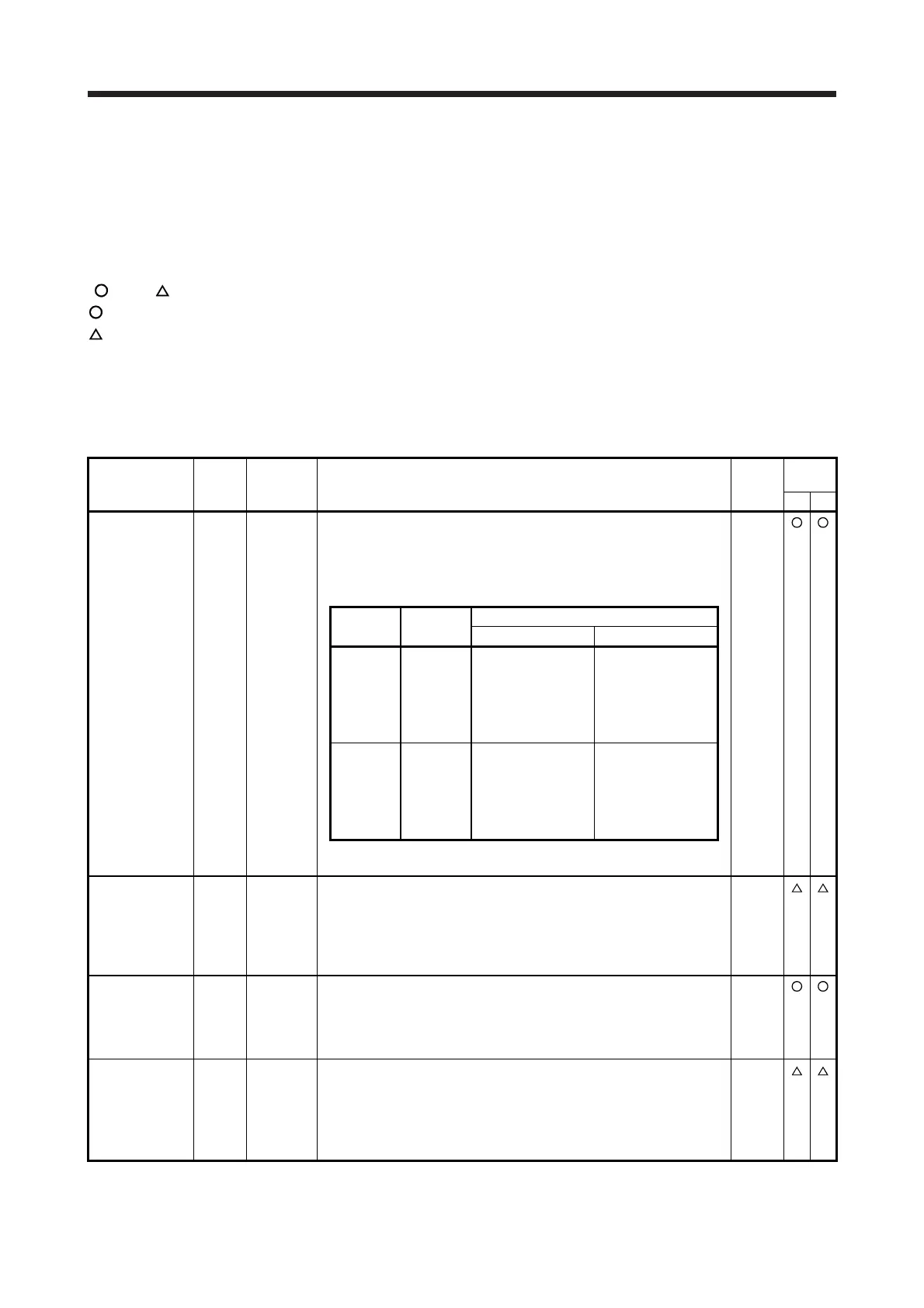
Forced stop 2 EM2 CN1-42 Turn off EM2 (open between commons) to decelerate the servo motor to
a stop with commands.
Turn EM2 on (short between commons) in the forced stop state to reset
that state.
The following shows the setting of [Pr. PA04].
DI-1
[Pr. PA04]
setting
EM2/EM1
Deceleration method
EM2 or EM1 is off Alarm occurred
0 _ _ _ EM1
MBR
(Electromagnetic
brake interlock)
turns off without the
forced stop
deceleration.
MBR
(Electromagnetic
brake interlock)
turns off without the
forced stop
deceleration.
2 _ _ _ EM2
MBR
(Electromagnetic
brake interlock)
turns off after the
forced stop
deceleration.
MBR
(Electromagnetic
brake interlock)
turns off after the
forced stop
deceleration.
EM2 and EM1 are mutually exclusive.
Forced stop 1 EM1 (CN1-42) When using EM1, set [Pr. PA04] to "0 _ _ _" to enable EM1.
When EM1 is turned off (open between commons), the base circuit shuts
off, and the dynamic brake operates to decelerate the servo motor to a
stop.
The forced stop will be reset when EM1 is turned on (short between
commons).
DI-1
Servo-on SON CN1-15 Turn SON on to power on the base circuit, and make the servo amplifier
ready to operate. (servo-on status)
Turn it off to shut off the base circuit, and coast the servo motor.
Setting [Pr. PD01] to "_ _ _ 4" turns the signal on automatically (always
connected) in the servo amplifier.
DI-1
Reset RES CN1-19 Turn on RES for more than 50 ms to reset the alarm.
Some alarms cannot be deactivated by RES (Reset). Refer to chapter 8.
Turning RES on in an alarm-free status shuts off the base circuit. The
base circuit is not shut off when [Pr. PD30] is set to " _ _ 1 _ ".
This device is not designed to make a stop. Do not turn it on during
operation.
DI-1
 Loading...

