- 29 -
4)
3)
5)
1)
2)
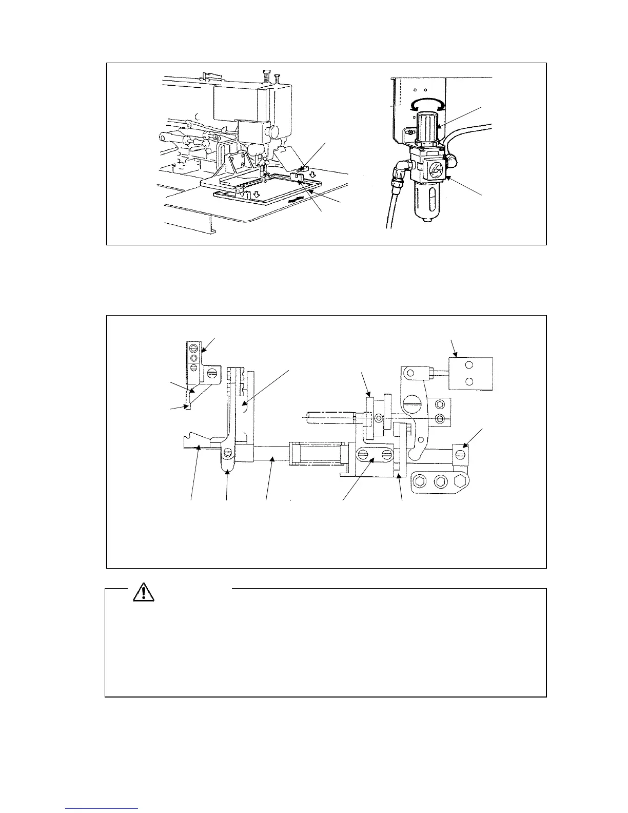
7-9 Adjustment of the thread trimmer
7-9-1 Structure of the thread trimmer mechanism
The thread trimmer mechanism of sewing machine is shown on the figure.
3)
4)
2)
1)
12)
11)
10) 9) 8) 7) 6)
5)
1) Knife mounting unit 2) Knife bracket 3) Trimming cam 4) Air cylinder
5) Stopper 6) Cam follower crank 2 7) Cam follower crank 1 8) Knife driving shaft
9) Driving crank 10) Movable knife 11) Stationary knife 12) Thread guide
CAUTION
★A lower shaft cam method is incorporated for the thread trimmer mechanism When adjusting the
sewing machine, if the thread trimmer air cylinder is in the operable state (state in which the cam
follower crank 2 arm is engaged with the thread trimmer cam) and the upper shaft is rotated, the
movable knife will collide with the needle and cause damage.
For avoiding this incident, always activate the air cylinder only in the regular trimming cycle which
the needle moves from its lower to upper position.
 Loading...