4
HARDWARE SPECIFICATIONS OF THE CPU MODULE
4.2 Basic Model QCPU
4.2.1 Part Names
4 - 25
1
OVERVIEW
2
SYSTEM
CONFIGURATION
3
GENERAL
SPECIFICATIONS
4
HARDWARE
SPECIFICATIONS OF
THE CPU MODULE
5
POWER SUPPLY
MODULE
6
BASE UNIT AND
EXTENSION CABLE
7
MEMORY CARD AND
BATTERY
8
CPU MODULE START-
UP PROCEDURES
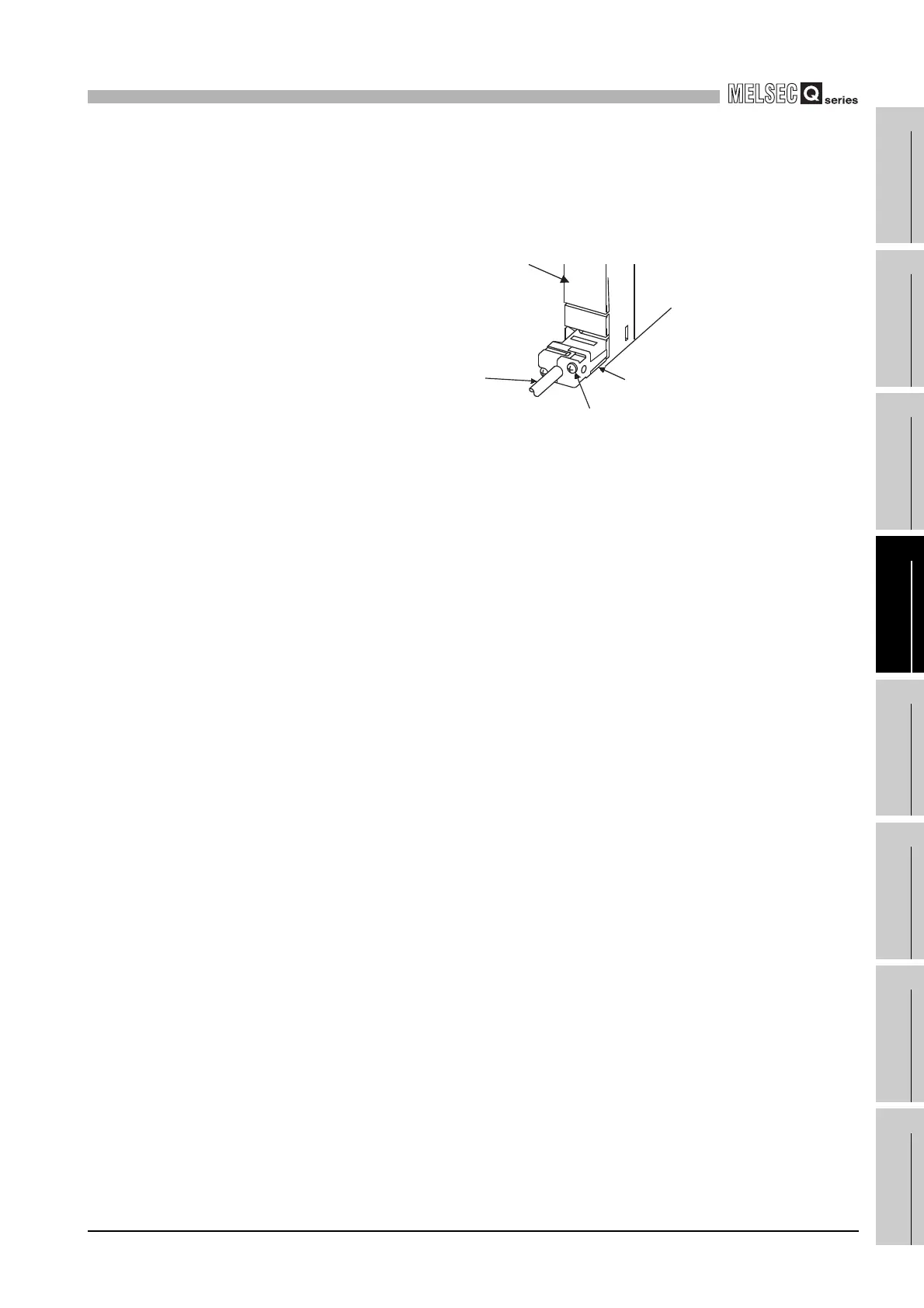
*1 : When a cable is to be connected to the RS-232 connector at all times, clamp the cable to prevent a loose connection,
shifting, or disconnection by pulling due to carelessness.
The Q6HLD-R2 type RS-232 Connector Disconnection Prevention Holder is available as a clamp for RS-232
connector.
*2 : Operate the RUN/STOP/RESET switch with your fingertips.
Do not use any tool such as a screwdriver because the switch part might be damaged.
Diagram 4.6 RS-232 cable fixing processing
Fixing screw
Q6HLD-R2
CPU module
RS-232 cable
 Loading...