5 - 26
5.3 Names of Parts and Settings
5
POWER SUPPLY MODULE
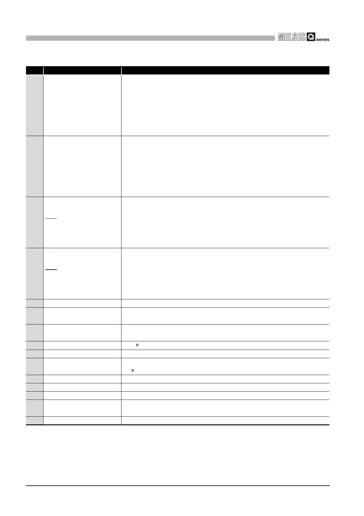
Table5.17 Part Names
No. Name Application
1) POWER LED
ON (green): Normal (5VDC output, momentary power failure within 20ms)
OFF : • AC power supply is ON, however, the power supply module is out of
order.
(5VDC error, overload, internal circuit failure, blown fuse)
• AC power supply is not ON
• Power failure (including an momentary power failure of 20ms or
more)
2) POWER LED
ON (green): Normal (5VDC output, momentary power failure within 10ms)
OFF : • DC power supply is ON, however, the power supply module is out of
order.
(5VDC error, overload, internal circuit failure, blown fuse)
• DC power supply is not ON
• Power failure (including an momentary power failure of 10ms or
more)
3) ERR terminals
• Turned ON when the whole system operates normally.
• This terminal turns OFF (opens) when the AC power is not input, a stop error
(including a reset) occurs in the CPU module, or the fuse is blown.
• In a multiple CPU system configuration, turned OFF when a stop error occurs in
any of the CPU modules.
Normally off when loaded in an extension base unit.
4) ERR terminals
• Turned ON when the whole system operates normally.
• This terminal turns OFF (opens) when the DC power is not input, a stop error
(including a reset) occurs in the CPU module, or the fuse is blown.
• In a multiple CPU system configuration, turned OFF when a stop error occurs in
any of the CPU modules.
Normally off when loaded in an extension base unit.
5) FG terminal Ground terminal connected to the shield pattern of the printed circuit board.
6) LG terminal
Grounding for the power supply filter. For AC input, it has one-half the potential of the
input voltage.
7) +24V, 24G terminals
Used to supply 24VDC power to inside the output module
(using external wiring).
8) Terminal screw
M3.5 7 screw
9) Terminal cover Protective cover of the terminal block
10) Module fixing screw hole
Used to fix the module to the base unit.
M3 12 screw (user-prepared) (Tightening torque range : 0.36 to 0.48N•m)
11) Module loading lever Used to load the module into the base unit.
12) Power input terminals Power input terminals for Q61P-A1 and connected to a 100VAC power supply.
13) Power input terminals Power input terminals for Q61P-A2 and connected to a 200VAC power supply.
14) Power input terminals
Power input terminals for Q61P, Q61SP, Q62P, Q64PN and connected to a power
supply of 100VAC to 200VAC.
15) Power input terminals Power input terminals for Q63P and connected to a 24VDC power supply.
 Loading...