5
POWER SUPPLY MODULE
5.3 Names of Parts and Settings
5 - 27
1
OVERVIEW
2
SYSTEM
CONFIGURATION
3
GENERAL
SPECIFICATIONS
4
HARDWARE
SPECIFICATIONS OF
THE CPU MODULE
5
POWER SUPPLY
MODULE
6
BASE UNIT AND
EXTENSION CABLE
7
MEMORY CARD AND
BATTERY
8
CPU MODULE START-
UP PROCEDURES
POINT
1. The Q61P-A1 is dedicated for inputting a voltage of 100 VAC.
Do not input a voltage of 200 VAC into it or trouble may occur on the Q61P-
A1.
2. Q64P automatically switches the input range 100/200VAC.
Therefore, it is not compatible with the intermediate voltage (133 to 169VAC).
The CPU module may not work normally if the above intermediate voltage is
applied.
3. Ensure that the ground terminals LG and FG are grounded.
4. When the Q61P-A1, Q61P-A2, Q61P, Q62P, Q63P or Q64P is loaded on the
extension base unit, a system error cannot be detected by the ERR
terminal.
(The ERR
terminal is always OFF.)
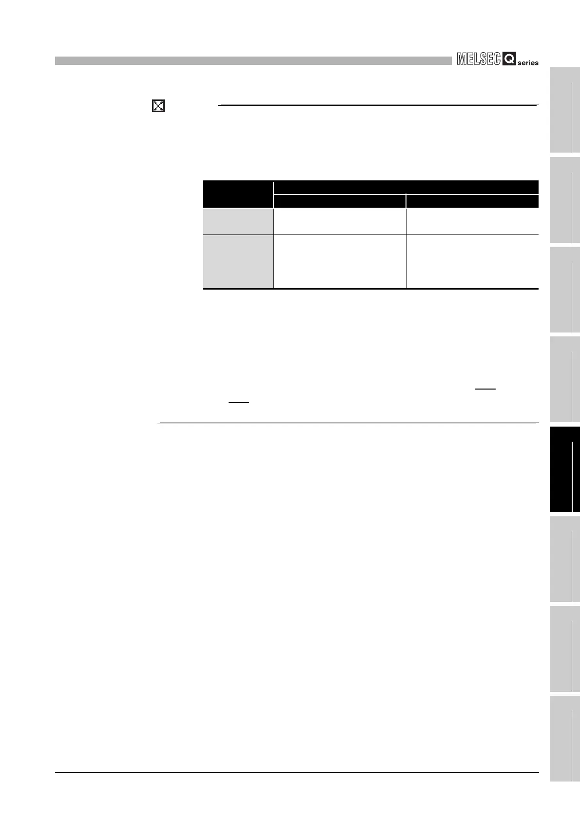
Table5.18 Precaution
Power module
type
Supply power voltage
100VAC 200VAC
Q61P-A1 Operates normally.
Power supply module causes
trouble.
Q61P-A2
Power supply module does not
cause trouble.
CPU module cannot be
operated.
Operates normally.
 Loading...