5 - 28
5.3 Names of Parts and Settings
5
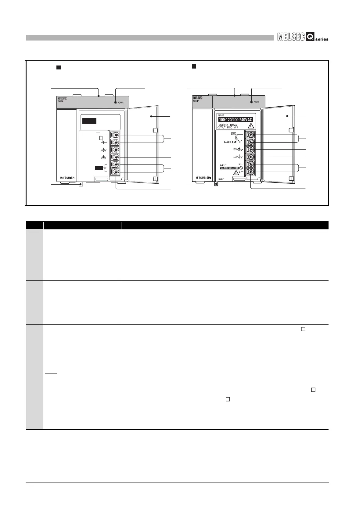
POWER SUPPLY MODULE
Diagram 5.7 Power supply module
Table5.19 Part Names
No. Name Application
1) POWER LED
ON (green) : Normal operation (5V DC output, momentary power failure of 20ms or
less)
ON (red)*1 : DC power is input but the Q63RP is faulty. (5V DC error, overload,
overload, internal circuit failure)
OFF : DC power not input, blown fuse, power failure (including momentary
power failure of 10ms or more)
2)
POWER LED
*
ON (green): Normal (5V DC output, momentary power failure within 20ms)
ON (red) : AC power supply is ON, however, Q64RP is out of order.
(5V DC error, overload, or internal circuit failure)
OFF : AC power supply is not ON, blown fuse, power failure (including
momentary power failure of 10ms or more)
3) ERR terminals
<When power supply is mounted on redundant power main base unit (Q3 RB)>
• Turned ON when the system on the redundant power main base unit operates
normally.
• Turned OFF (open) when the Q63RP fails, the DC power supply is not input, a
CPU module stop error (including a reset) occurs, or the fuse is blown.
• Turned OFF (open) when a stop error occurs in any of the CPU modules in a
multiple CPU system.
<When power supply is mounted on redundant power extension base unit (Q6 RB)
or redundant type extension base unit (Q6 WRB)>
• Turned ON when the Q63RP operates normally.
• Turned OFF (open) when the Q63RP fails, the DC power supply is not input, or
the fuse is blown.
Q64RP
Q63RP
11)
12)
2)
4)
5)
6)
8)
9)
10)
10)
11)
1)
3)
5)
6)
7)
9)
12)
Q63RP
INPUT
24VDC
24G
+24V
24VDC 0.5A
L
ERR.
(LG)
(FG)
OUTPUT 5VDC 8.5A
INPUT
MAX 65W
24VDC
 Loading...